![]()
![]()
![]()
|
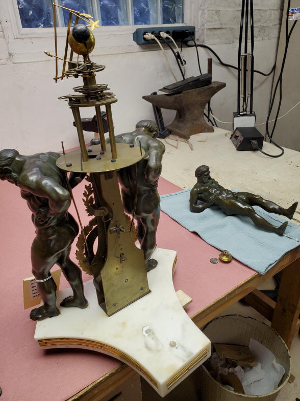
Unknown, Paris, France, 1786. Single train 14 day duration, tic-tac, one-half second pendulum. Movement with front gilt plate surrounded by three bronze figures of Atlas holding a glass celestial sphere; within the sphere a clockwork-driven orrery with plants to Saturn including working Earth-Moon system. Restoration photos of the clock. The disassembly and observations. This clock had suffered an accident in what appears to have been a long time ago. There was severe damage to several of the wheels in the orrery and the main arbor upon which all of the lower concentric planetary tubes were mounted was slightly bent. No damage was seen to the statuary or base, both of which are quite heavy; each statue is solid bronze weighing in at 5 lbs. (2.27kg) each. Total base and compliment of statuary comes in at 20 lbs. (9.1kg). Which leads me to believe that the the orrery was probably dropped and damaged when removed from the clock, otherwise there would have been more damage to the clock plates and likely the base and statuary. However, having said this it does appear that the orrery mounting plate had some re-working in the parts used to mount it to the top of the clock front and rear plates; so it could have been mounted to that plate and maybe the clock when it was tipped over. It is unlikely to have been dropped or the damage would have been greater. The reworking of the attachment points of the orrery support plate could also have been from the loss of the original parts. I am confident, given the perfect location of the aperture through which the orrery drive comes through from the clock to the orrery, and that there are no open or closed holes on the plate, that the plate itself is original to the orrery and the clock. What is clear is that the clock itself has a fair share of open holes, particularly five on the front plate; the rear plate has two. One hole is threaded, one is not even a hole but a crudely, unevenly oval hole. In addition both front and rear plates have a hole very close to the screws that secure the orrery mounting plate to the top of the movement plates and those I am confident were holes for the locating pins for the parts that were originally used to secure the orrery support plate to the clock. The type of clock frame plate design as well as wheel and orrery drive layouts have other extant examples, in particular one in the collection of the Worshipful Company of Clockmakers, now in the British Science museum. The is a discussion to compare and contrast these examples later in this presentation. |

| The clock begins to be disassembled. Notice the folded arms on the orrery in the first photo. Three arms fold up representing Mars, Jupiter and Saturn. This necessary to allow the neck of the celestial glass sphere opening to clear the orrery when removed or replaced. It should be noted that after the glass is put in place, it is quite difficult to reach through the space between the glass globe and the orrery mounting plate to safely unfold those arms. All examples of this type of orrery surrounded by a glass sphere have a folding provision for the orrery. The next photo shows the first of the three statues removed. |


| Side and three-quarter rear view of the Atlas statue. |


| The three statues removed and each carefully numbered as they relate to their position on the marble base. Those numbers are mirrored on the base. |

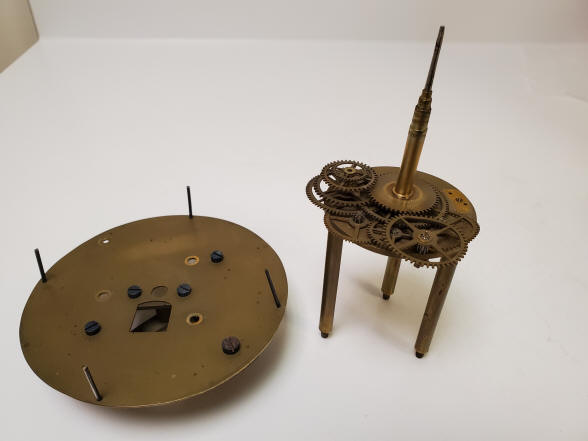
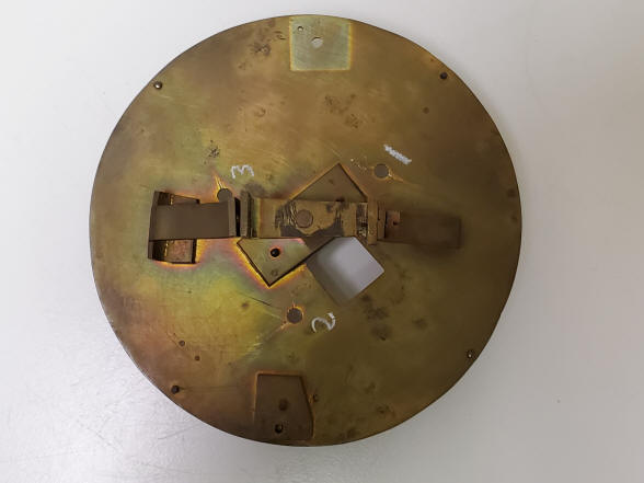
| The underside of the base clearly shows that the clock mount was drilled and then later re-drilled to fit it into position. There is no corresponding re-drilling of the statuary. next the orrery mounting plate, left, and the orrery (some parts already removed). |


| The first photo shows a rectangular shim plate that fits under the rear clock movement plate making the clock tilt slightly forward, next photo. This may have something to do with the re-drilled holes for the clock mount to make it fit properly in the middle of the three statues. |

| These photos show some of the damages to the wheel work of the orrery. |

| The first photo shows another view of the bent wheel work, the center post is bent a bit to the right. The second photo shows the shadow of the wheels directly above the orrery table. This illustration is not dirt but a layer of corrosion. It appears that some of the corrosion came from above, perhaps as acidic pollution or other contaminants that may have been produced nearby. In any case the wheels would have had to have been frozen in place for may years, probably a hundred or more. The entire movement was later brought to a fine finish, however this part I only did a light polish as I thought this witness marks was an interesting story to the object's history. |

| The first photo shows the underside of the orrery table, it appears the oxidation is far less here as the blued screws are in good condition. All of the screws are marked to correspond to an area identically marked next to each screw. Notice all of the scratch marks around the open hole to the left of the center spur gear. This is the pivot hole for the drive arbor from the clock below. It appears that this had slipped out of the pivot on occasion and was forced back in without removing the pins that secure the legs of the orrery table to the support table below to allow it to be moved without scratching the underside surface. The second photo shows what appears to me to be an improvised set of parts on the underside of the orrery support plate used to connect the support plate to the top of the clock's movement plates. |
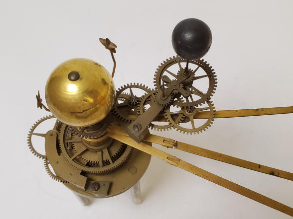

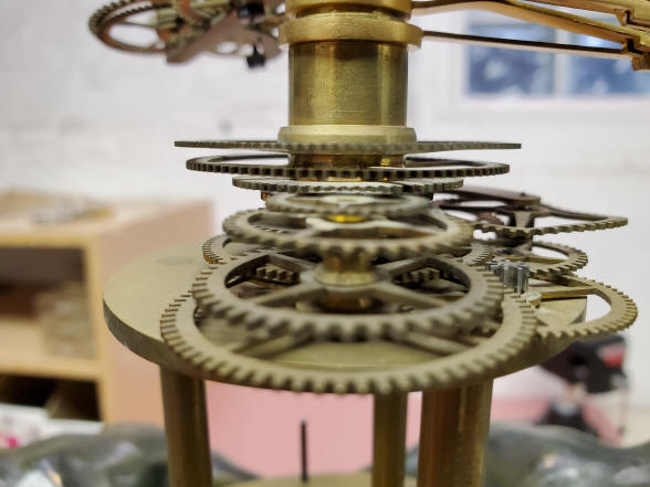
| The first photo shows the reassembled orrery with the repaired wheels. The second photo shows the three planetary arms for Saturn, Jupiter and Mars. Mars was missing its star and one was recreated. |

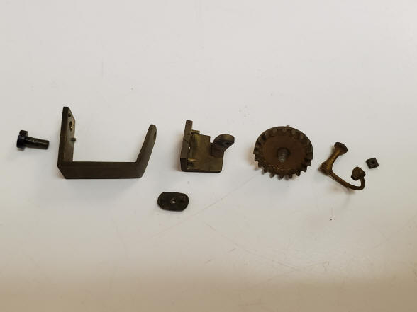
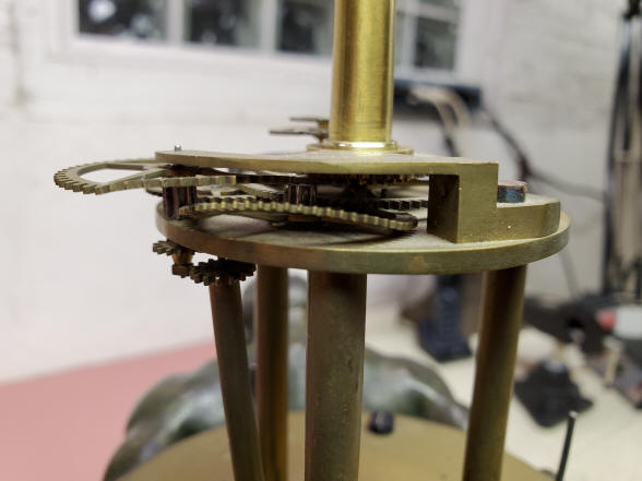
| In the first photo one can see the spur gear which meshes with a crown wheel that is connected to the demonstration crank. As received, it was not possible to turn the demonstration crank fully around. Under magnification one can see a couple of problems here. the upper arrow points to a misshapen tooth. The lower arrow points to a prior repair that involved a poor tooth replacement effort. One can see it was soldered into place, but little effort was made to make the correct tooth profile. Both problems were resolved with a little judicious bending and delicate filing resulting in a smooth cranking for the demonstration function. The second photo shows an exploded view of the crank and support structure. The crank is tiny, less than 3/4", (2 cm). It must encounter no resistance. |
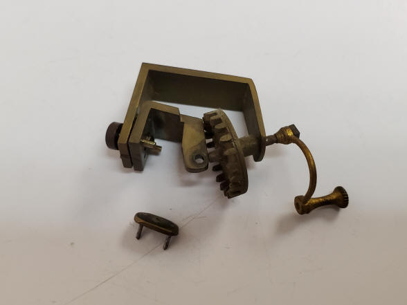
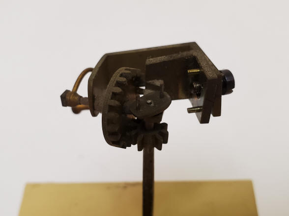
| These photos show the crank assembly, it is all fairly complex and somewhat, in my opinion, a bit sloppy in construction. It is, however, identical to other examples so is an original design. |


| The spring is removed from the barrel. I was curious to see if it was signed and it was in three places, the second photo showing the most legible, Slanotam?. It also was dated, 1786. If anyone has any information on this name, I'd appreciate any help in identification. |

| The clock and orrery now fully disassembled. The globe was moved to the table for just the photo. Because of the complexity of this project I had decided to completely reassemble it to be sure everything was working before a second disassembly for the finishing and polishing. |

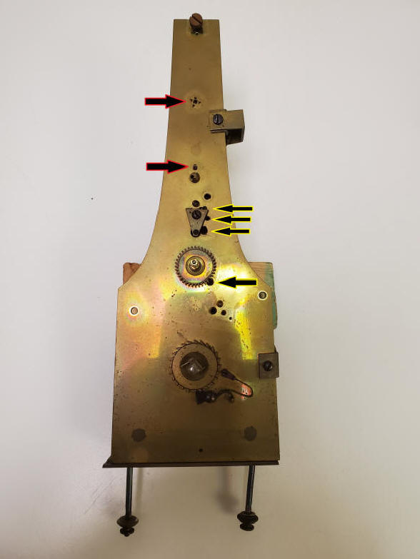
| These photos examine some anomalies found on the clock frames. In the first photo there are four open holes, white arrows, and the same holes shown in the second photo, black arrows. The third hole from the top is a crudely made semi-oval, unfinished. The rest are holes, but without threads or oil sinks, none are mirrored through the rear plate. The two upper holes marked by yellow arrows in the first photo are mirrored through the plates, and curiously the hole in the front, represented by the uppermost arrow in the second photo has four triangular punch marks, presumably to close the hole, but what is actually made is more of a square hole, the mirrored hole on the rear plate is round. The two black arrows in the first photo show where the suspension thread adjustment arbor is located. The thread is wound around the arbor on the rear just above the pendulum where the right arrow indicates, and the other end is a small square for a key to wind and unwind the thread, thus adjusting the length of the pendulum and its rate. The pendulum suspension thread was attached to this arbor as found. I will unravel the mystery of the mirrored holes later. |
| If one looks carefully at the screws at the very top of the front and rear plates there is a tiny hole just below the screws. I believe these were originally made for locating pins that were part of the original setup for the attachment of the orrery support table. The current arrangement has no provision for a locating pin and so the holes are empty. |

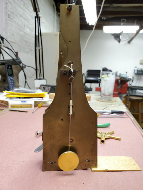
| The first photo shows the locations of two empty holes on the rear movement plate. Again, the hole shown by the arrow at the top is mirrored on the the front plate with a punched hole made square. The movement now undergoes testing to determine duration and rating. The original pendulum was missing so a cheap pendulum was purchased on line and cut to the approximate size. The bob weighs about .45 oz. The rod had tape wrapped around to just clear the rectangular crutch opening. The orrery was reassembled and attached to be sure the clock would drive it and everything was in running order before the finishing and polishing process. |
![]()
![]()
![]()