Construction now begins on the body of the remontoire also known as the
cage. This is the structure that holds the remontoire wheels that drive the escapement.
This type, which is based upon Bernard-Henri Wagner's
design of 1850 is what I call the 'swinging frame remontoire'. While the original
design used one frame, we have incorporated two remontoire in two frames, each which will
independently drive an escape wheel (there are two) and both remontoire are driven from a
common differential. This has never been done before so to test the design we first
constructed a working mockup out of plastic back
in April of 2006.
We first begin with design drawings to get a a consistent pattern for
the parts that is to be carried out throughout the movement. This originated with the overall frame and its curvilinear aspects along
with sharp spurs along the convex curvatures, and for lack of a better term I call the
'Condliff look' after the famous 19th century skeleton clock maker James Condliff of
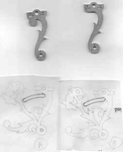
England. The first photo shows once again the importance of the original wood mockup as
our starting point. The two parts on the top are taken from that model. The style of
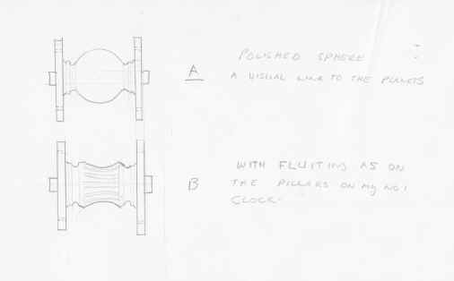
pillars are considered in the next two drawings, details are decided later, but chosen was
a concave over the more popular convex shape. At this stage it makes little difference as
these will not take their final shape until later. The actual pillar design, which must be
consistent throughout, is settled upon in the fly fan assemblies. A technical issue is
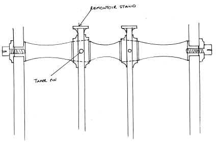
addressed in the third drawing regarding the way the main remontoire cocks will be secured
to the main frame pillar. We used a taper pin to ease the repeated
reassembly that will
be required throughout the remontoire construction; estimated to be over 100 cycles.
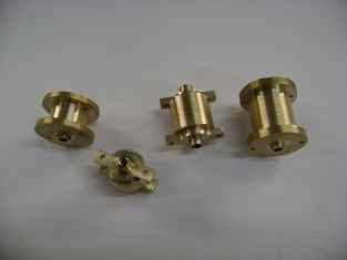
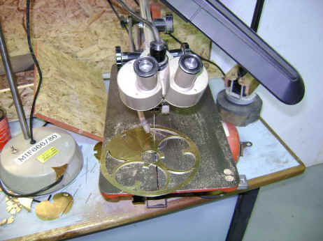
Lastly the design is drawn onto metal for cutting. All flat stock work is cut with a
scroll saw by hand under a stereo microscope.
There is no computer aided design or manufacturing.
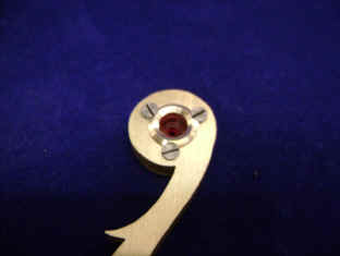
Fabrication of small parts. The third and fourth photo show the chatons which are used
throughout the entire going train. The balance of the movement will be jeweled and needs a
total of approximately 450 pivot jewels as well as many specialty shapes for escape
pallets and other sliding-friction points. The fifth photo shows a change we made in
eliminating the extra 'bulb' in our initial cut, this is seen in the shaded areas of the
parts. Last photo final parts of part of the remontoire cage.
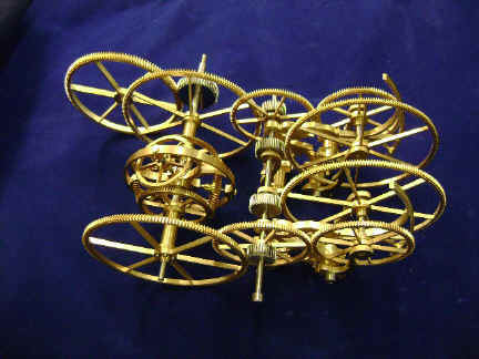
The frame is assembled with the wheels. The area in the first photo showing a
rectangular depression on the silver cylinder circled will be filled with a shaped jewel
for the remontoire cam arm to rest upon. Next the two remontoire shown side by side. Last
photo is the completed system. The wheel in the upper left hand corner is the input drive
from the main weight. This is not the way it will appear in the movement since the parts
are laying on a flat surface. But take away the input drive wheel and it does make the
assembly look like a cute race car!


