Fabricate strike snails and begin strike hammer linkages - January 2014
The first photo is a rendering of the hour snail. Buchanan had mentioned to me that he was thinking of a nautilus design, but I had no idea how far he was going to carry out thi s concept. Look at the additional four cutouts near the snail hub. This is what the natural nautilus shell displays when cut through with a saw, but is rarely if ever duplicated in a clock. Also the exterior steps exhibit the same organic design with the curved ends behind each of the snail steps.
The first photo shows the brass blanks before fretting out. Next the completed nautilus designed snail cams. 
 These photos show the heart shaped cam used to keep the snail in step within the petit sonnerie repeating mechanism. The first photo is the old solid heart shaped cam that has been on the movement until now. Buchanan has placed the skeletonized cam over the solid one for comparison.
The first photo shows
the heart cam mounted to the snail; next with that assembly mounted to the
drive wheel in the last photo.
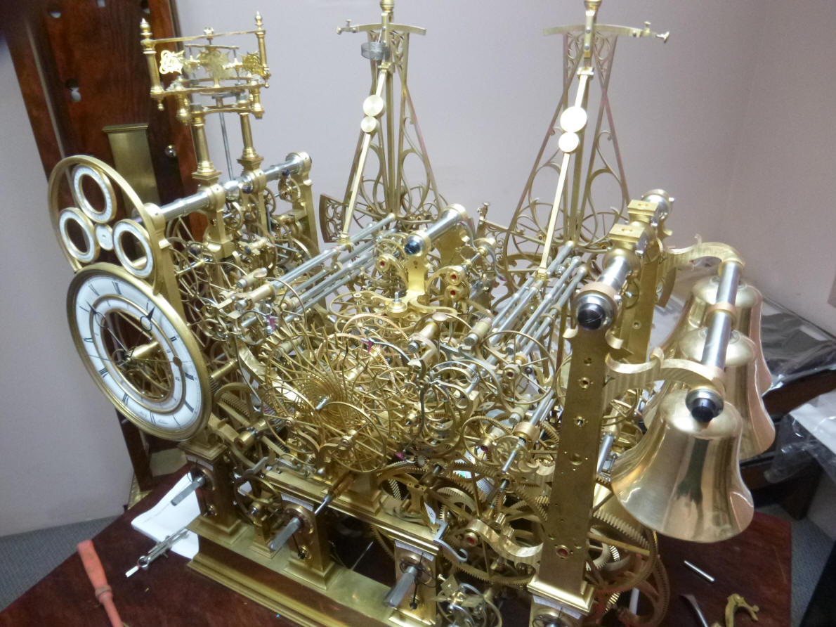
The snail is now installed into the movement.
Immediately we see a problem. Here the visual complexity of the clock is
working against us. An ordinary wheel is fine to be ‘part of the forest’.
But these snails are special and we need them to stand out. Several ideas
were discussed. The first was some form of damascene on the surface, next
having the edges knurled, next plating them in rhodium or rose gold, and
finally using the EDM machine to put a fine matte finish on the surface
similar to that which will be on the outside surfaces of the mainframe
pillars. I like this last idea best since it will provide unity of design
between these parts and the pillars. It also is one of the least labor
intensive of the alternatives. 
 Now begins the fabrication of the strike lever and hammer system. This is the initial design schematic for the strike lever system. It will employ a grasshopper design using compound, articulated levers rather than the simpler, conventional lever type found on most movements. The grasshopper design allows for less friction and pressure forces on the operating parts.
Next we explored the finish for the birds. We could go
with brass, steel or blued steel. I ruled out brass since there is already
so much brass colored material in this vicinity. Steel was rejected for the
same reason. Blued steel was chosen since we are using this same finish for
the strike levers and racks, circled area. The blue color choice will
complete the connection between those components and this final extension to
the bells.
The strike levers are now being fabricated. Note the file
in the background of the first and second photos. Buchanan aligns all of the
same sized levers together and uses the file for final shaping thus
achieving a uniform set of parts. The parts are initially cut out from a
steel sheet in the same jewelers saw used for the rest of the flat stock
used in this movement. The third photo shows the eight completed levers.
The levers are now being machined to accept the spacers
and roller bearings upon which they will pivot.
The levers are now positioned into the movement for the
first trial fit. I like the way these vertical curvilinear levers provide
juxtaposition against the straight horizontal arbors.
The levers begin to be assembled. First Buchanan has to make about fifty custom screws. The fourth photo shows the assembled hour and quarter strike lever sets. After these are tested for fit and functionality the brass spacers are turned for their final decorative profiles.
|