|
Structural support sub base redesign, fabrication and finishing of most dial hands - January 2021 This month Buchanan continues to finish up the project. A redesign clock frame sub base was proposed and a mockup surround to hide the sub base were made. Most of the dial hands are fabricated and finished.
Original sub base steel box frame next to the clock in November 2012. Note the stage of the machine's construction compared to this month.
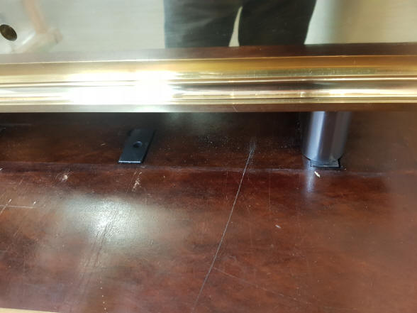
First photo shows the completed box frame within original clock stand, second photo one of eight countersunk support blocks through the table top upon which the clock rests. From the beginning of this project the clock was designed to be weight driven. The original four weight set had a mass of 220 lbs. (100kg). The clock's base is composed of four main sections, the front, rear and side pieces. While these base rail pieces are substantial, they are connected together with hidden fasteners and while these provide a seamless look to the base they are not strong enough to prevent some movement between the pieces under the load of the weight set. Any movement would cause misalignment in the machinery mounted to the frame resulting in catastrophic failure. The photos here were taken in November of 2012 during construction of the clock stand. The first two photos show the sub base consisting of a steel box frame. That box frame is then set into the stand and the clock sits on the eight blocks which have holes for locating pins attached to the clock base, third photo. The last photo shows how a table top with eight cutouts for the blocks allow the clock base to look as if it rests on the wood table top, but is actually floating just above the wood; resting on the steel box frame. The stand added another 120 lbs. (55kg). In November of 2019 it was decided to change the clock's drive from weight to motor springs. This was done for a variety of reasons as outlined in the November 2019 installment, but the elimination of 340 lbs. was a plus cutting down the total weight of the machine by about 57%. The clock could now rest upon any stout table top. But, what if the table top was not perfectly flat, or over time deviated from being flat? A test was made to see if the frame was stiff enough under those circumstances even without the weight set to keep its integrity. Unfortunately the answer was no. So a sub base was still a necessity. At first the idea was to remove the box frame from the stand, grind off the attachment points and use it as the base. Several issues complicated this option, the main one was that the clock could no longer be simply placed on the base and in turn on a table top since the box frame was far larger than the footprint of the clock's base. The base support has to be hidden. So any table would have to have a cutout made in the top to countersink the box frame. The fact that the box frame was about two inches thick, would requite it to somehow be supported in the table top hole since no normal table would have a top so thick. Also the support becomes critical as the box frame must be a millimeter or so above the surface of the table so the clock frame floats above as originally designed. This method worked fine when the box frame was supported by the steel surround of the original stand, but becomes problematic when required in a wood table top with improvised fastening provisions to the rest of the table. Trying to keep the needed 1 millimeter clearance over a wood top when the approximately 250 lbs of the machine was applied was risky and unlikely to be successful.
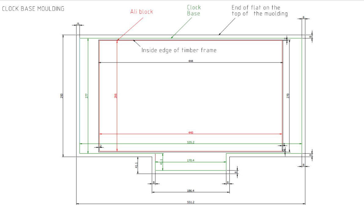
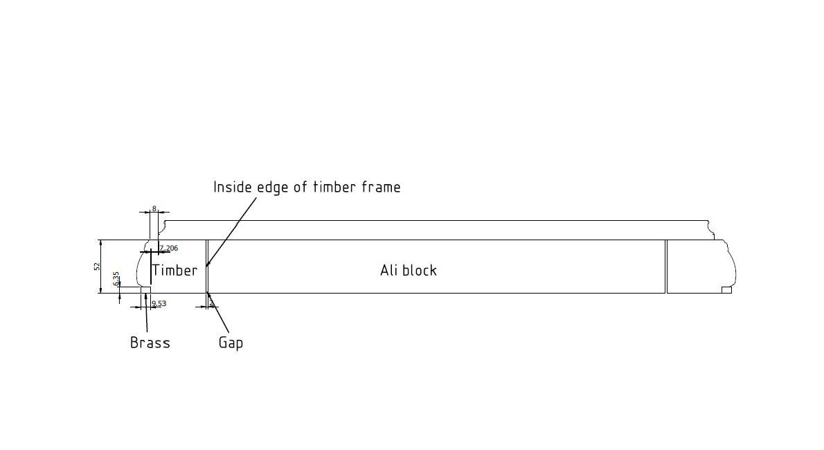
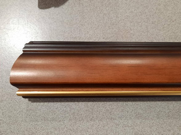
Design drawings for decorative base molding that will surround the aluminum support base beneath the clock's main frame.
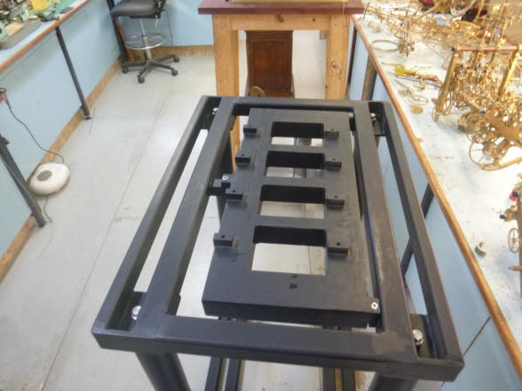
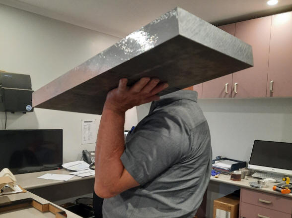
Raw aluminum block for the sub base before machining. Next the mockup surround to hide the base.
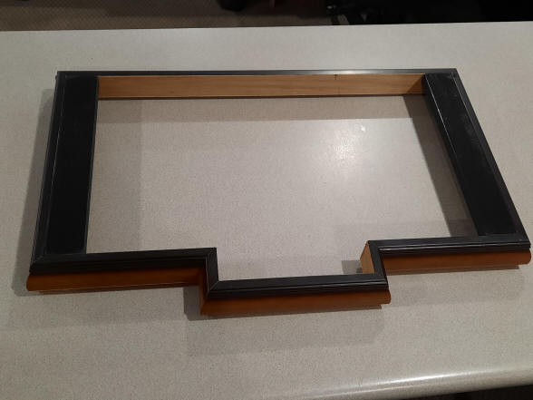
Once again Buchanan had invented a brilliant and elegant solution. The original box frame was discarded and a block of solid aluminum was substituted. That block will be milled to fall within the footprint of the clock's base frame. The other three photos show a mock up made of store-bought picture frame material to hide that block within the footprint of the clock's base.
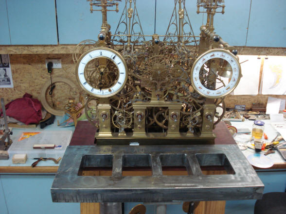
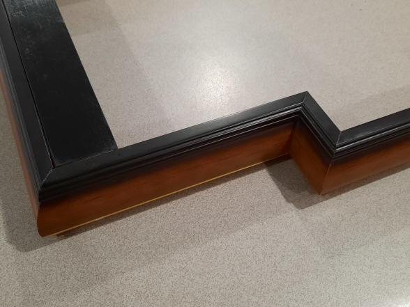
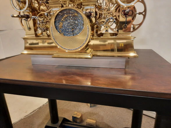
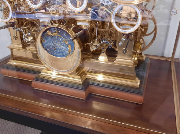
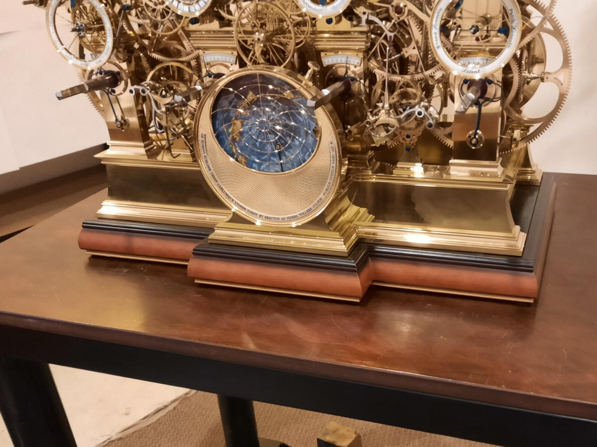
The first photo shows the sub base aluminum block in place, next photo shows the decorative surround. The planisphere overhang is not a problem as it is firmly attached to the main base rail.
Close up of the mockup base surround. It can simply be placed over the aluminum sub base block. There will be four locating pins for the clock to properly align with the sub-base support. I think it is both a practical and beautiful solution. The sub base will be on a three-point contact ensuring that it will never rock regardless of the condition of the table top. The permanent surround is now being made to look like the mockup, complete with a brass trim at the bottom rather than the gold paint on the picture frame rail.
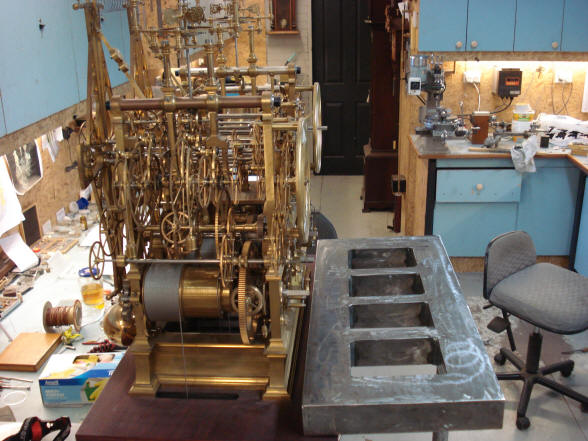
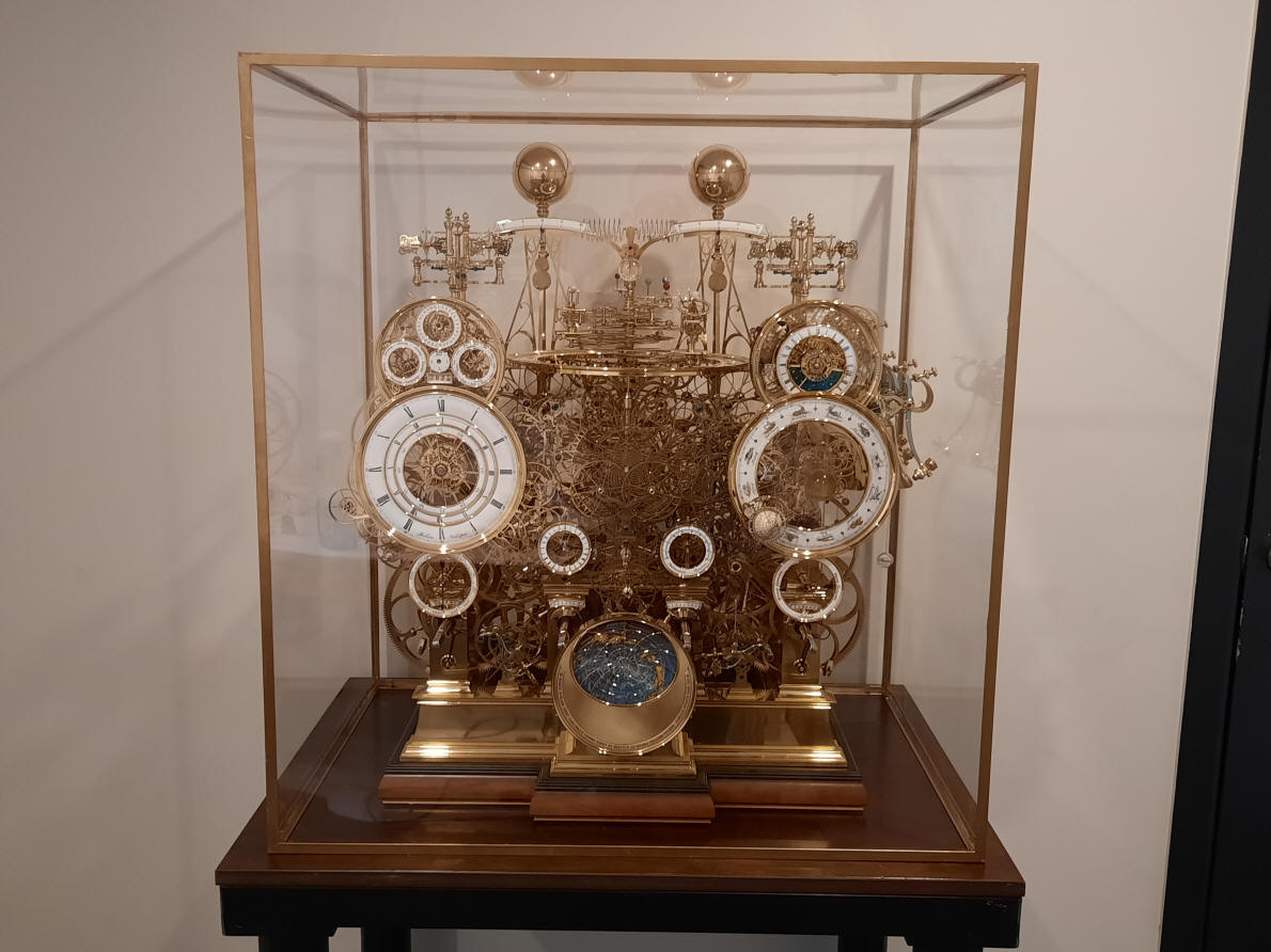
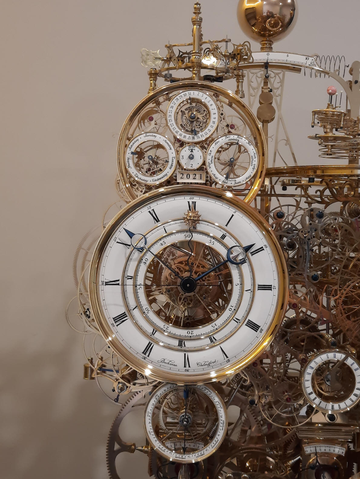
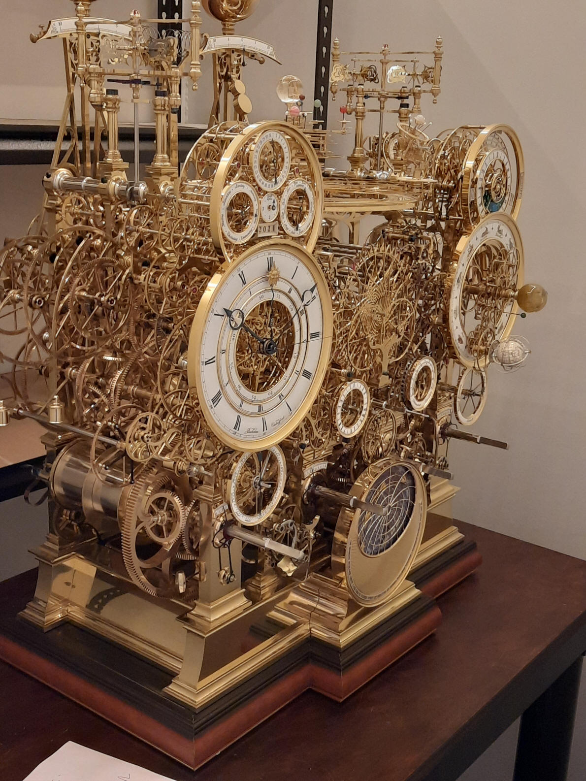
Front elevation of the machine on the mockup base surround and temporary case.
Buchanan now turns to the fabrication and finishing of the dial hands
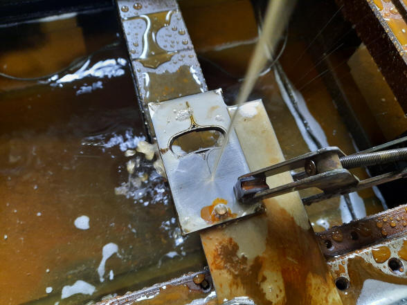
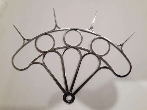
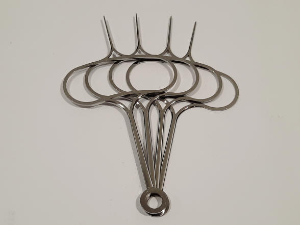
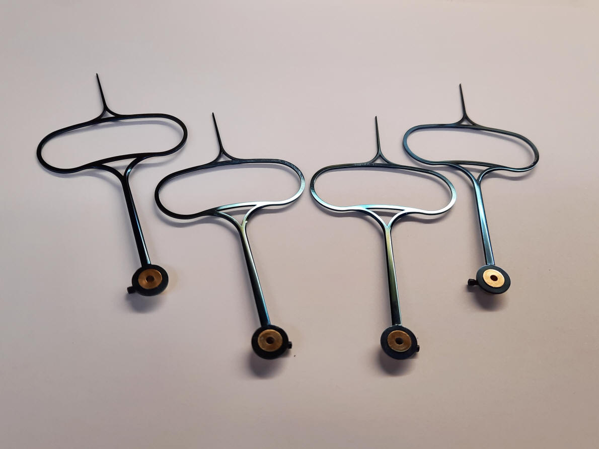
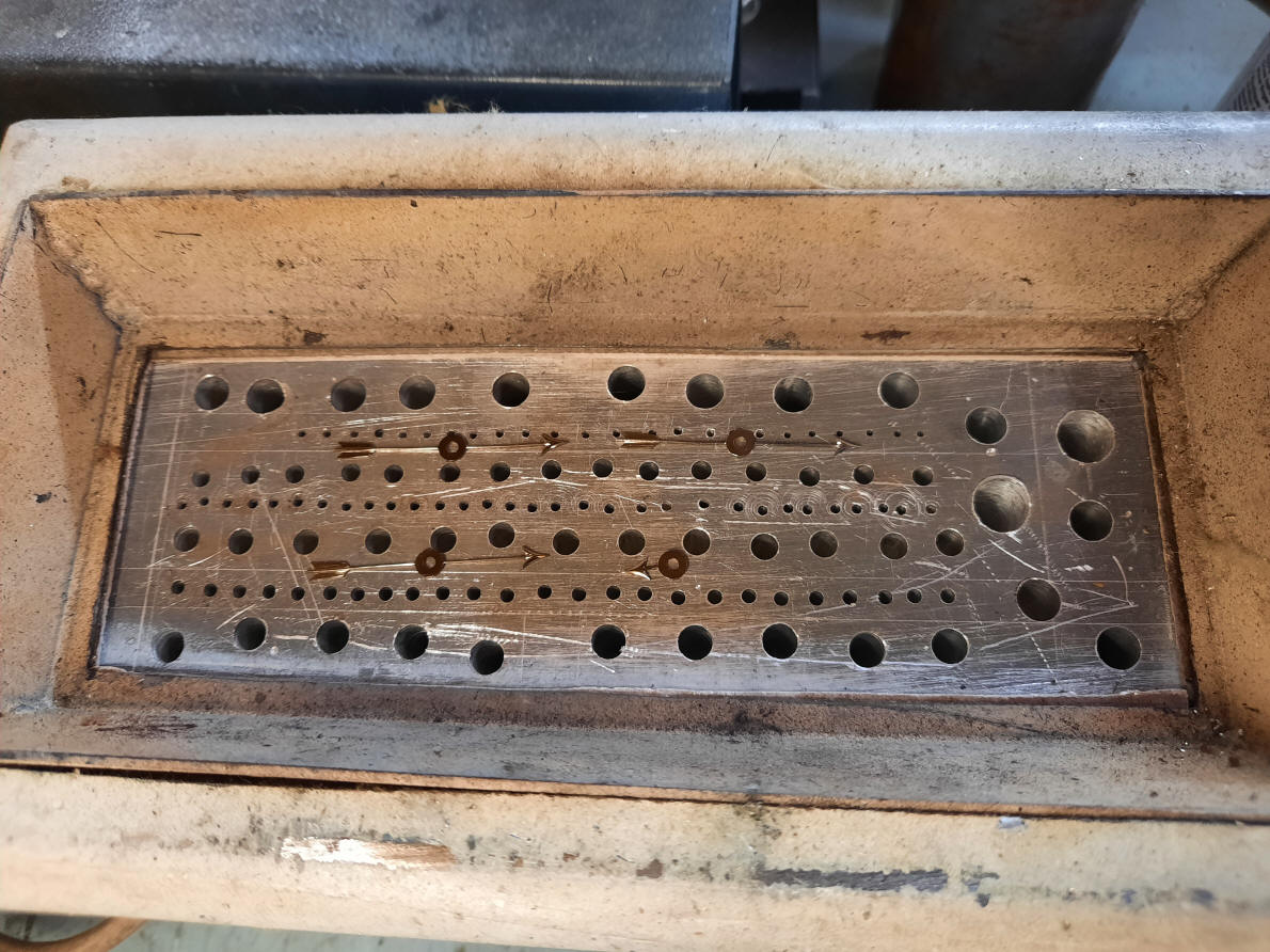
The first photo shows Buchanan using a spark erosion machine to cut a set of of four hands for the state of wind indicators. Here is a case where replication using a CAD-CAM controlled process not only makes the fabrication more efficient, but produces perfect replication.
Here a dial hand is being cut from a steel blank using a CAD-CAM wire spark-erosion machine. If one looks closely at the steel blank it is actually a hacksaw blade. It turns out that the steel these blades are made from will blue up beautifully in the oven.
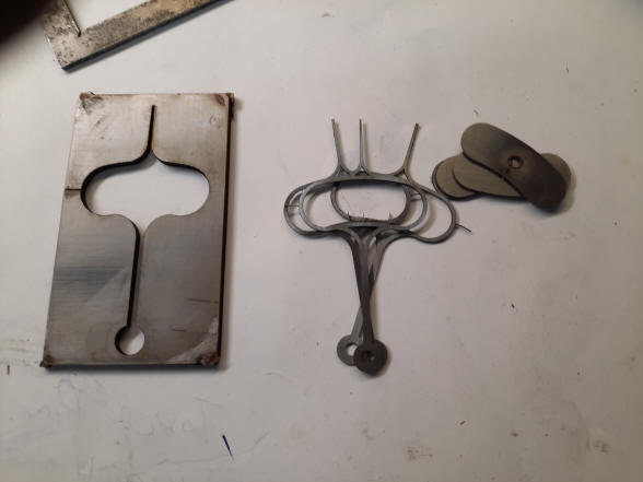
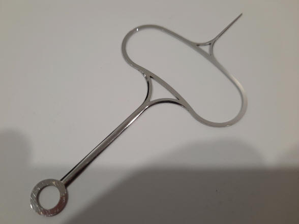
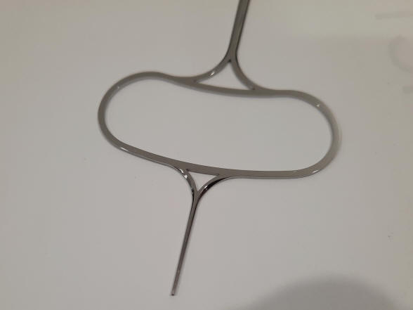
These two photos show close ups of the state of wind hand before bluing.
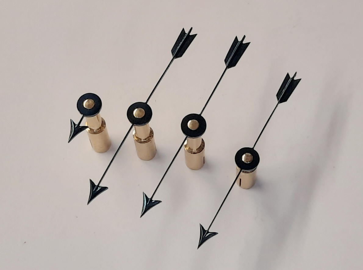
The state of wind hands finished. Note the set screw on the collet, this allows for alignment of the hand to the state of wind dial to match up with the Geneva stop that controls the number of turns of the winding barrels.
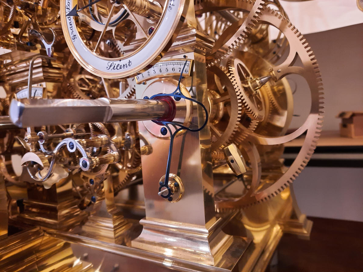
A state of wind hand installed along with the eight-day enamel indicator dial; this photo reveals the shade of electric blue color that is consistent on all blued hands and screws throughout the machine. These indicators were designed when the clock was weight driven and so were somewhat superfluous. One could look at the weight to estimate the state of wind. But now that the machine is spring driven they serve a vital function. A fortunate stroke of serendipity.
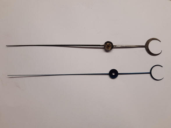
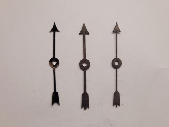
These two photos show a comparison of Buchanan's design next to an antique example. The first photo has Buchanan's example below and the second example to the right. In each case Buchanan's is slimmer.
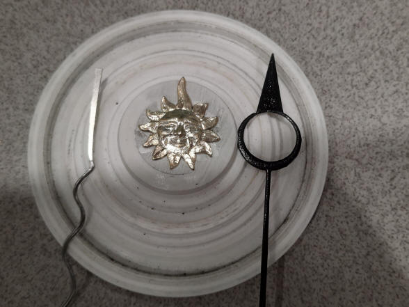
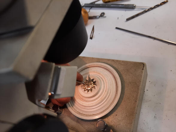
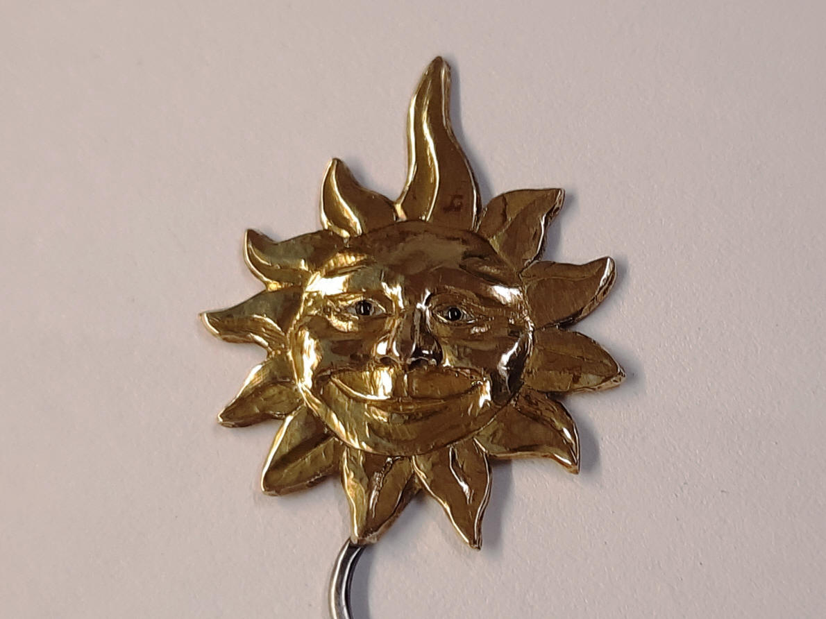
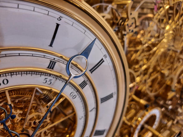
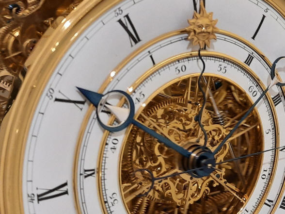
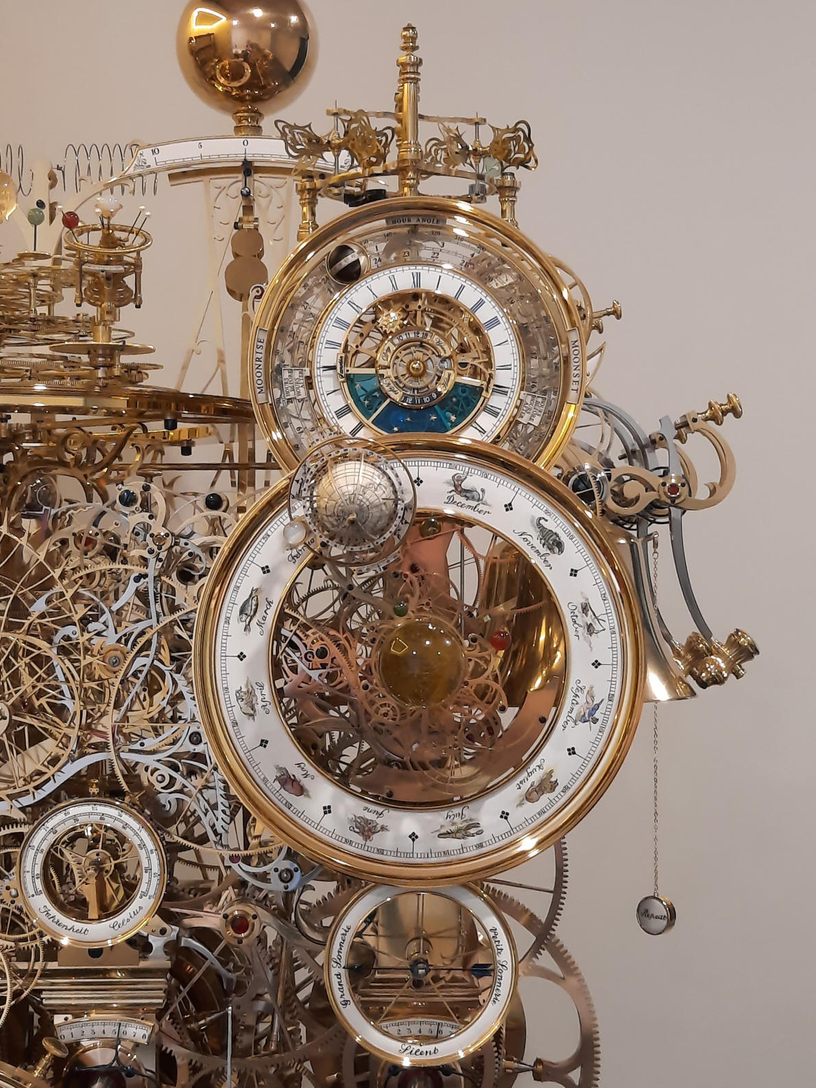
Here we see the wizened and contented smile of Mr. Sun. His face is gold plated, and pupils blue ceramic balls. Remember the detail one sees here is actually on a piece that is only 1/2" (1.1cm).
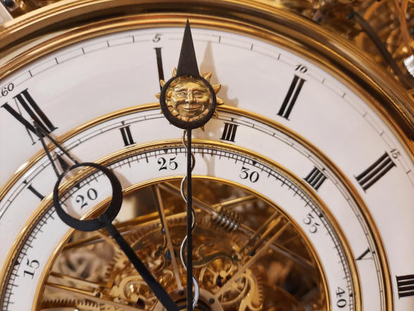
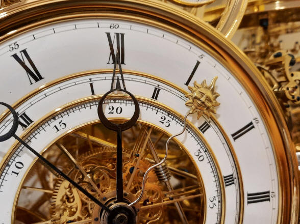
The first photo shows Mr. Sun behind the mean solar minute hand and so "Sun time" and mean solar time of the regular clock dial are exactly the same, so the Sun is exactly at its zenith directly overhead at 12:00 Noon and will occur on the dates of April 15, June 13, September 1 and December 25. Next the reading between the two shows the equation of time to be 15.5 minutes ahead, that is, the Sun looks to be fast. This means that when the Sun is at its zenith in the sky, it is still 15.5 minutes yet until noon on the clock dial, conversely at Noon clock time, the Sun is already 15.5 minutes past its zenith. On a day to day observation the Sun hand and mean solar minute hand appear to be moving at the same speed relative to each other, however as time goes by throughout the year the Sun will reach a maximum just over 16 minutes 33 seconds ahead and then move towards the mean solar minute hand, fall behind it by just under 14 minutes 6 seconds and then reverse course moving ahead by 3 minutes 43 seconds, and again fall behind by 6 minutes 25 seconds; this pattern repeats annually year due to the eccentric orbit of the Earth around the Sun and the tilt of the Earth to the ecliptic. Therefore four times per year the sun will appear exactly in the middle of the clocks minute hand circle. One might wonder how one can tell the small differences of the Sun's deviation from its zenith, but the use of a sun dial will readily reveal this discrepancy and was as valuable in time keeping as were clocks in the 18th century when this horological complication was popular. A description of the equation differential module and further explanation of the equation of time concept can be seen when the equation differential work was fabricated in May 2009.
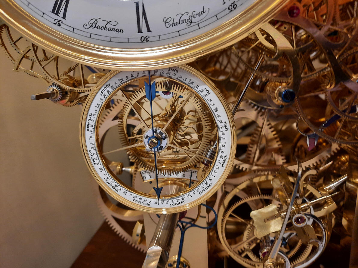
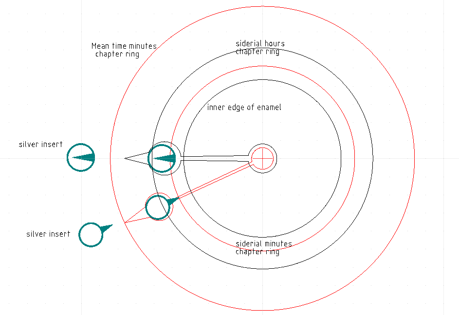
We now turn to the design of the mean solar time and sidereal time hands. The initial design had a separate 24 hour dial for sidereal time. This is the standard way sidereal time is displayed, given its relation to mean solar time where sidereal time is exactly 24 hours behind mean solar time over a one year period. A sidereal day is 23 hours 56 minutes 4.0905 seconds or 23.93446 hours compared to the mean solar time of 24 hours. I wanted a way to relate the two readings in a way that was easily understood. I attended an exhibit sponsored by the Antiquarian Horological Society at Cal Tech in Pasadena, CA in November 2013 and saw a clock by Thomas Tompion that had an outer clockwise rotating chapter ring of the mean solar time in relation to the inner fixed sidereal time chapter ring. In Tompion's clock the sidereal time was the focus, so it was stationary and the mean solar time dial rotated clockwise and the two times were read off the same set of dial hands. The gold hand This can be done if one remembers that after the first six months one has to add 12 hours to the nominal 12 hour dial. In our clock we reversed the priority and made the mean solar time dial stationary with the inner sidereal dial moving counterclockwise, again allowing one to read both times with the same set of hands. The illustration above shows the design for the hour and minute hands that have a pair of inserts so these two hands will be able to produce four readings. The sterling silver inserts will read sidereal time and the black surrounds the mean solar time.
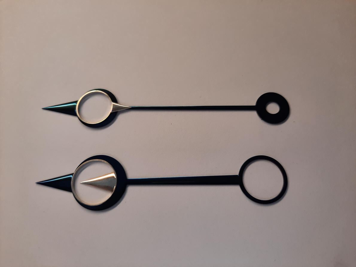
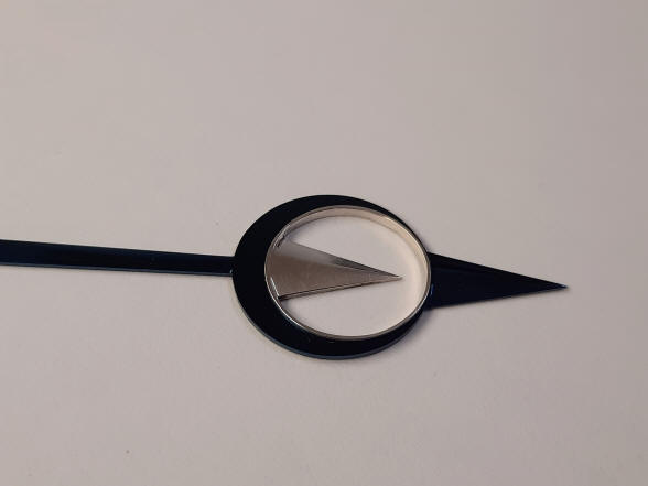
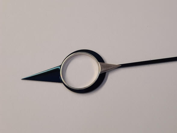
The three photos above shows the finished set of hands.
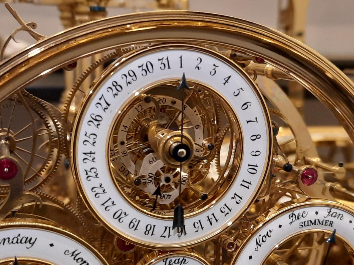
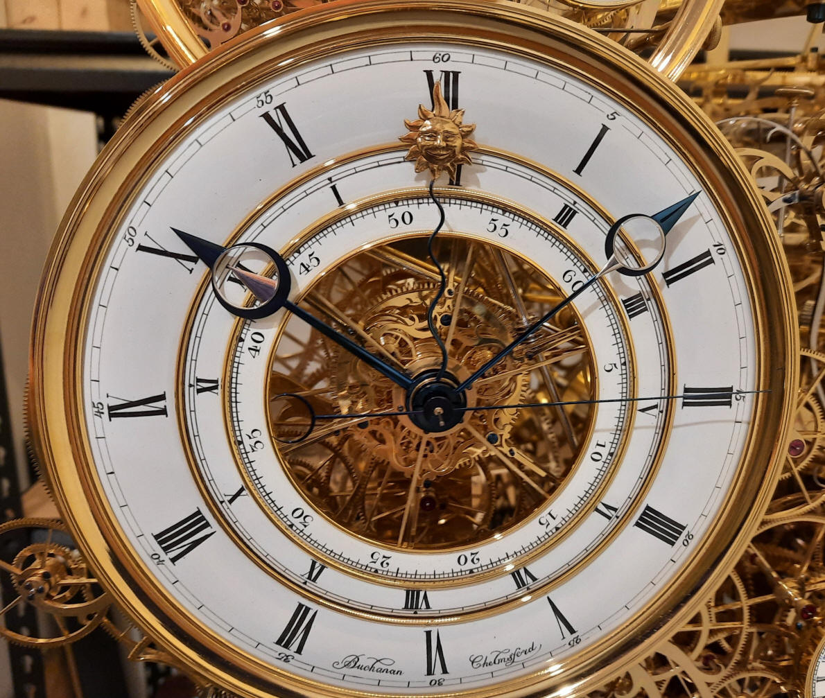
Finished mean solar and sidereal time dials. It was decided that the normal practice of having the shaft of the equation dial hand be gold, was instead blued, as gold disappeared due to the brass color behind.
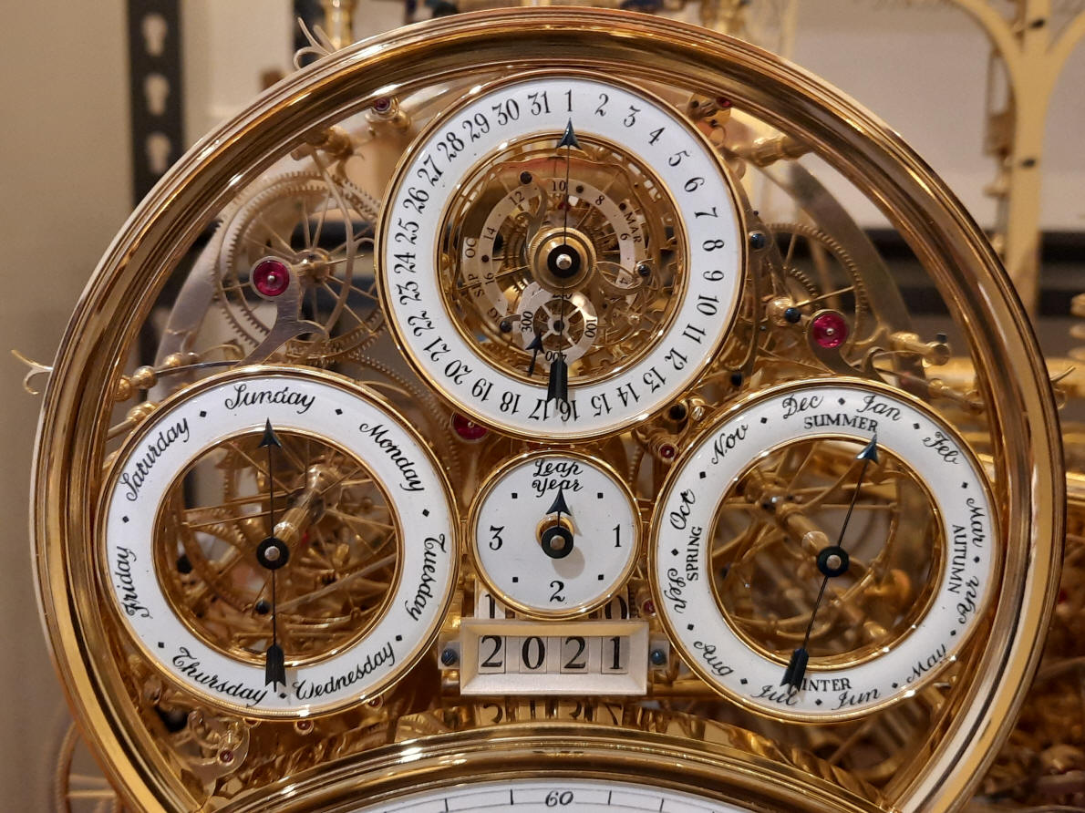
Finished left hand dial set. World time and demonstration dial to the right is not yet completed.
Finished right hand dial set.
Left three-quarter elevation with machine mounted to mockup base. |
![]()
![]()
![]()