Redesign of movement frame - March 2009
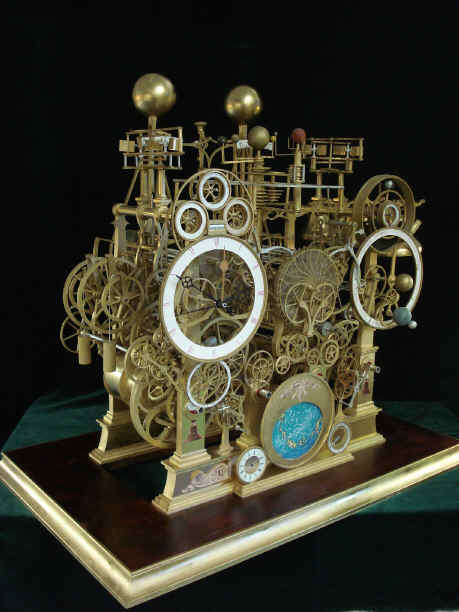
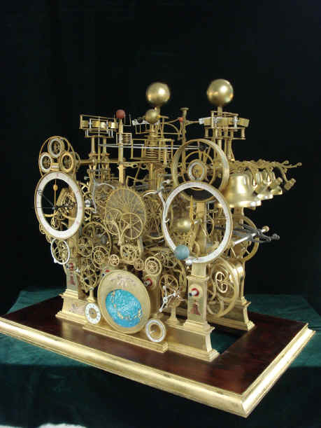
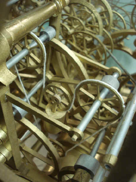
The clock up to this point has been slowly assembled with its wheels between plates made of Plexiglas. As the complexity grew I began appreciate the beauty of this complexity and started to think about the type of frames we were contemplating for this project. The frame as it stood was of a conventional plate and spacer design. While these plates were to be extensively cut out, they still would, by necessity enclose all of the wheels presently between those plates. Back in December of 2008 I asked B his thoughts on this. He mentioned a 'pillar' type design. He has actually made a few preliminary drawings in this direction back in May of 2006, but they were not well fleshed out and so the plate and spacer design which was later turned into the working mockup was chosen. The time was soon to come where work on the frames had to begin and certain decisions on where wheels would be planted between the trains depended upon the type of frame chosen. I authorized him to make a new effort on a design that would more fully reveal the wheel work while reducing frame mass. Below is the result of three weeks of design and mockup fabrication. I immediately realized that this change was an improvement toward my goal of greater visibility of the movement. It also brought the style of the clock from the area of a unique but undefined style to that with a definite French Empire skeleton clock look; a more recognizable and classical design. The base now has a more tapered look in relation to the maximum width as displayed by the two largest dials. We also rearranged the planisphere layout. There was always the slight bothersome illusion that with the two dials within the mask of the planisphere it looked too much like a face with the dials for eyes and the oval opening a gaping mouth. The first thing to notice is how all the wheel work around the planisphere is now out in the open. B. does this through what he calls 'dumb shafts'. Here the wheel is mounted to an arbor that is secured only by one end to the frame with the opposite end unattached. This complicates the use of jeweled pivots. I also felt that this departed too radically from conventional wheel planting design. I asked B. to use a minimalist design to secure both arbor ends. The result is what I call the 'vine' design. We now have what B, says is an organic looking motif growing on a classical type of facade, shown in the photo set below. In the first photo the vines are employed on the left, with dumb shafts on the right of the planisphere; and a closeup of this design in the second shot. I also had suggested B. add side rails to the base to match the fronts and add a bit of a corner reveal as shown, third photo. The fourth photo shows the addition of the Robert Robin remontoire that will trip the celestial train. This will add a third and different remontoire as well as another fly to initiate once per minute. There will also be additional reveals on the front and rear rails. Last photo a side by side comparison. Judge for yourself.
Astro_03-09_frame_vid.mpg Astro_03-09_frame_vid2.mpg Astro_03-09_frame_vid3.mpg Astro_03-09_frame_vid4.mpg Astro_03-09_frame_vid5.mpg
|