Fabrication of pendulum balance assemblies - antifriction wheels and their plates, November 2008, page 1
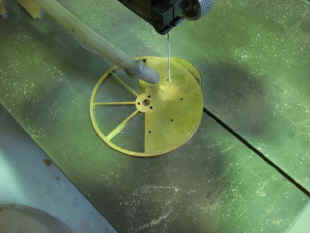
Each antifriction wheel is cut out as are all wheels and all but the largest parts by hand on a small jewelers saw with special customized blades that are made thinner and sharper than are standard. A binocular magnifying scope is used throughout.
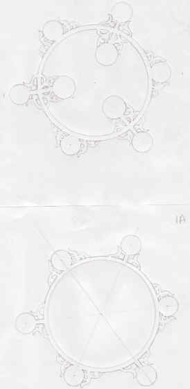
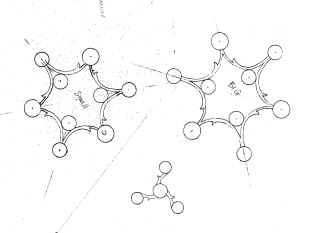
The fabricator made about a dozen drawings and winnowed those down to the three he felt were best to present as a design for the antifriction wheel plates. At first pass they all looked good to me, but it was impossible to know which would be best, so I asked him to make each design in wood and put it in place on the mockup to gauge the merits of each. Each design has a pair of plate designs, one for the rear arbor support (larger) and one for the front (smaller). Only the rear plates were made up.
Below is the the first drawing made up in wood with the metal antifriction wheels and then placed on the mockup. The thin spokes and delicate rims of these wheels are a hallmark of this firm's design.
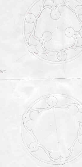
Next set show the second design.
Next show the third, most plain design. The surprising thing was that when these designs were actually tested on the mockup that instead of thinking all the designs were pretty good, it turns out all of them were bad! In fact the more ornate the design the worse it looked on the mockup. The plates were clashing and competing with the balances as well as the antifriction wheels behind. This was bad enough, at this stage with the balances still in their original fairly plain design. These were later redesigned to a more ornate pattern that would have been spoiled by these plates.
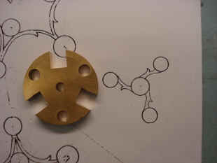
Next we went to a plain design that was first described in April of 2004. It was better as far as offering less competition to the surrounding parts. However, it looked misshapen and a bit awkward. In the last photo below one can see the original mockup concept for this part on the left hand balance. I decided that this original design was the best after all. It offers the least distraction in relation to the other parts.
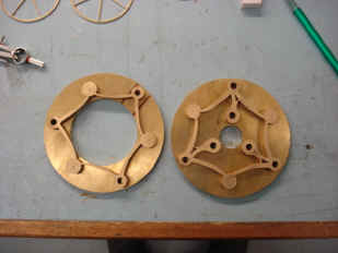
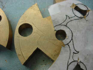
The problem with choosing the original design was that the fabricator had already cut out a large hole in the plate which was to become the part and these plates had also already been fitted with six jeweled chatons! He tried to salvage the parts by making the original design to fit the parts as cut. The results are below. It was an improvement, but the lack of symmetry was still there. Now to be fair, this is not the fault of the designer, the placement of the parts demand that one sector be a bit farther from the center than the others. It's just that this as well as the prior design tended to exaggerate this weakness. The first three designs, while unacceptable, did have the circular ring which did a good job of hiding this detail.
The first photo shows this design on the mockup. In the end there was no choice but to scrap the parts and start over. A new design was prepared, center drawing, and a wood mockup made, right photo. Notice how the one extended sector, while still there with its length unaltered from the earlier designs, is now neatly disguised. The small part in the lower center of the drawing is the complementary design for the arbor center and end spacers.
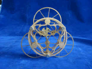
The redesigned part is now mounted in the mockup. Center photo, the new part - right, and original - left. While the original part has the virtue of having a smaller overall profile; revealing the most of the parts behind it, it still has a bit of misshapen symmetry. It also is hugging the center and obscuring an area that I would like to be a bit more open to inspection. Is the new part better than the old? I think so, but in this case it boils down to a matter of taste. The point of showing this design development in detail is to illustrate how parts for the movement are developed. It is not always smooth and often contains surprises. It also entails a lot of extra work to draw, fabricate, try and photograph designs before metal is cut. And once again it proves the invaluable tool that the mockup provides. Last photo shows the beginning of the antifriction wheel plate's fabrication.
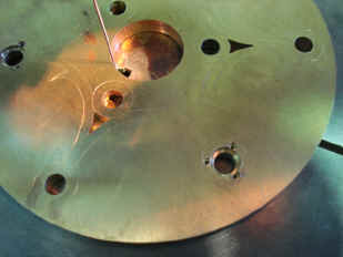
The center is cutout. Then the outline. Note how thin the blade is in relation to the fairly thick brass plate.
Notice how the part is cutout as a whole from the blank; in one pass! How many folks could do this? Most fabricators would be sectioning off the waste material while cutting the outline. Next is the finished part attached to arbors.
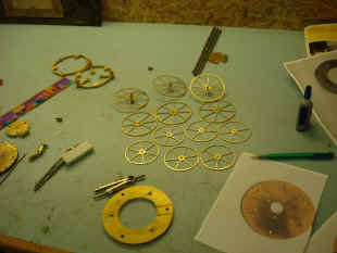
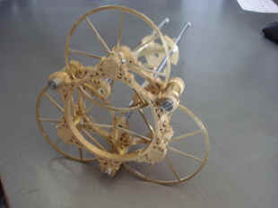
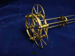
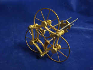
Finished rear antifriction wheel pendulum balance support. The larger rear wheels have eight spokes, with the smaller front wheels having six. The position of the assembly as shown is the way it will be installed in the movement. The pivot for the pair of top wheels are slightly oversized from a conventional bearing in relation to its arbor pivot. In this way as the pendulums swing through their approximate 15o arc, the antifriction wheel pivot will roll along the upper portion of the pivot hole, never sliding against the surface. This can be achieved since the antifriction wheel will rotate less than 2o. And this means that the pendulum fulcrum points as well as the escapement will not need oil. See illustration above. It is a shame, on the other hand, that one will not really be able to see the antifriction wheels move. Fortunately, this is not the case with the antifriction wheel sets on the escapement assembly.
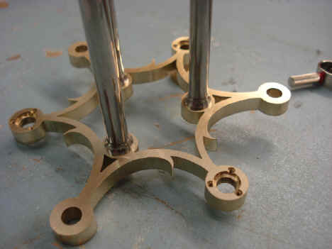
Now the arbor center arbor spacers are cut to final shape. Pattern is traced, scribed and cut by hand.
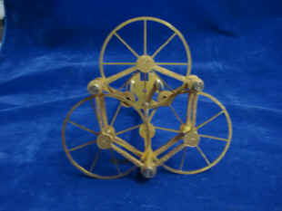
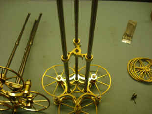
Below are photos of the torsion components that will keep the balances in perfect alignment. Since we are have mounted the balances upon antifriction wheels, we do not have the natural constraints that a conventional pivot hole containing an arbor pivot with a shoulder would have. Alignment is critical since the grasshopper escapements are mounted directly to these balances and any lateral movement of these would cause to escape pallets to misalign from the escape wheels. The two end pieces shown in the second photo mount to the ends of the center, hollow fixed arbor. The center piece, which is tied to the wire, is fixed to the hole in center spacer shown above as well as the first two photos in the set just below these. The threaded ends will have the adjustment knobs which will allow precise alignment of the pendulum balance.
The center spacer now in place. The fulcrum spacer lays in line with the knops on the antifriction wheel arbors. When the pendulum is swinging the spacer will rock neatly between the knops. Last photo shows the rear end of the finished pendulum arbor.
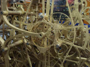
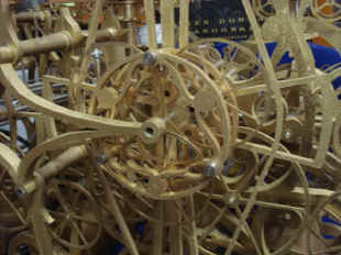
Below a close up of the inner antifriction wheel plate revealing the complexity of the pendulum system. The screws will later be polished and blued. The second photo shows the rear end cage with the eight spoke wheels, in the background the smaller six spoke wheels.
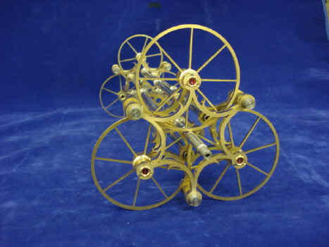
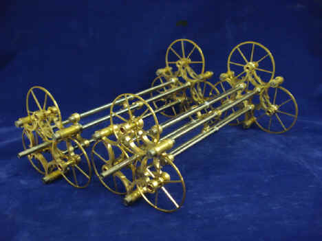
Photos of the completed pendulum arbors in three-quarter profile. These are the most complex pendulum arbors I know of with just over 320 parts for the pair. This system serves what would be the suspension spring or knife edge in a conventional design. The actual pendulum balances (which would be the rod and bob in a conventional design) will be attached to these just behind the inner, rear antifriction wheel plate.
Astro_11-08_vid.mpg Astro_11-08_vid_2.mpg Astro_11-08_vid_3.mpg Astro_11-08_vid_5.mpg
|