|
POUVILLON RESTORATION PROJECT - April 2012 Complete restoration of zodiac precession, and year indication complications In this section we complete the restoration of the zodiac precession and the year indication complications.
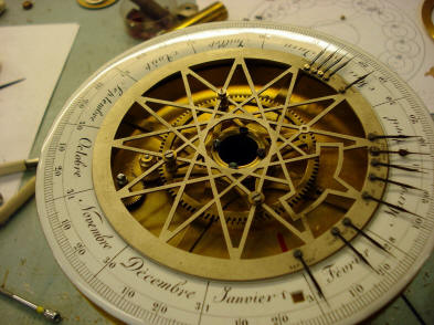
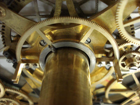
I had concerns if
Buchanan had considered how the drive for the zodiac precession will deal
with the fact that the orrery will be able to be demonstrated in reverse.
This is an issue as the drive for this as well as the year indicator ring is
driven from the arm that holds Mercury. So what happens when Mercury is
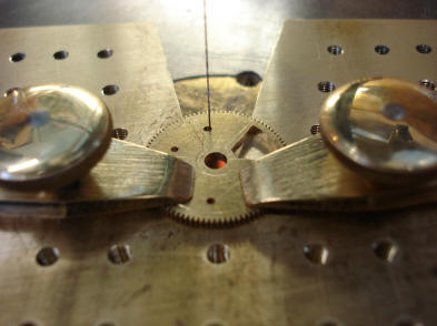
rotated in reverse? The first photo above shows a bypass clutch devised to
deal with this eventuality.
The center wheel arbor
is now fitted with a key-square which will be used to make the adjustment to
the year indication ring. The spring washer shown previously is under this
wheel. When one wants to adjust the ring the key is placed over the square
and depressed. This pushes the wheel out of mesh with the far right drive
wheel, but still in mesh with the pinion connected to the ring. The next
photo shows the position of this adjustment square within the existing
tellurian structure. It is nearly opposite from the existing adjusting
square Pouvillon used to move the thirteen indication pointers for the
various movable feasts of Easter and is of the same key size.
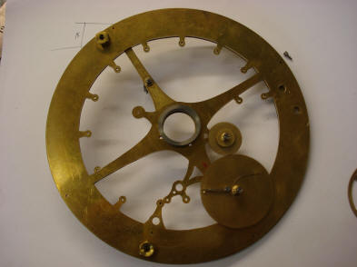
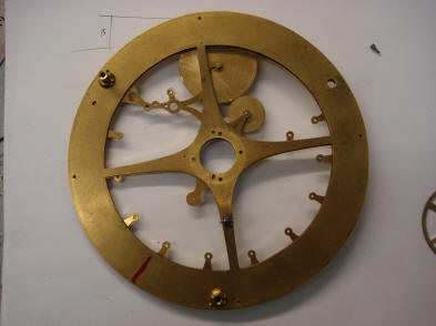
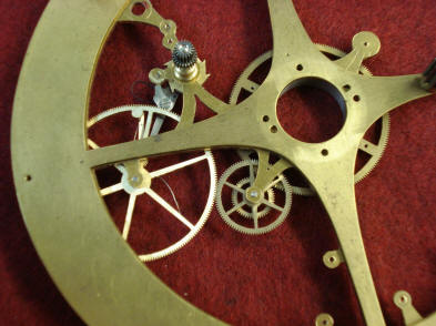
Here we have the main
frame cut out which will hold all of the wheel work for the year and zodiac
precession complications. It is designed to be as hidden as much as possible
within the existing tellurian superstructure. In fact the two are
superimposed in these photos. The first shows the new structure over the
original, and the second the mechanism flipped over to show Pouvillon’s
structure over the new. This was purposefully designed to make the new
restoration of these functions as unobtrusive as possible. These third photo as
well as the first one below are close ups of what is shown below and above
the plane of the tellurian base and with the inclusion of the main drive
wheel which is located at the center. The two pairs of holes drilled at the
2 and 7 o’clock positions will hold the brackets that will contact the arms
upon which the planet Mars is attached on the orrery. It is this planet’s
rotation that provides the drive for the two complications. We had to choose
Mars as it is the top of the collet-nest that provides the attachment points
for all of the planets outside the orbit of Earth as represented in the
orrery.
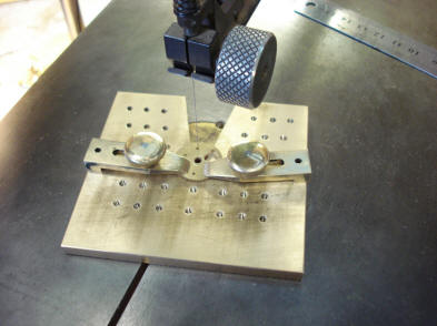
The last two photos show the laborious process of cutting out all of the wheel spokes. There are 18 individual wheels. However, on 13 of those wheels, the pinions are not the solid, conventional form, but an additional spoked wheel. So in reality there are 31 wheels to be spoked for the two restored complications. These wheels are too small to be held by hand and so are held in a jig on the bed of the jeweler’s fret saw, last two photos . Here we see the initial
few wheels completed. The first photo shows a view from the side showing the
new plate and the second from the side showing Pouvillon’s tellurian support
plate. The two are nearly perfectly superimposed.
The wheel spoking process continues in these photos.
The first two photos show the completed wheel works.
The third photo shows the completed two complications which fit completely
within the existing tellurian structure.
From the three-quarter side view they are nearly impossible to see. We see
to it that our restoration will still be in keeping with the known
historical photographs.
Even from the top, most of the new wheel works are hidden.
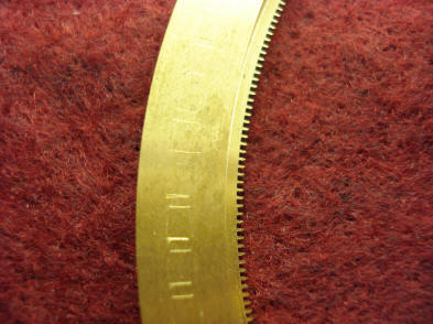
The next job is the engraving of the year indications on the ring. The first photo shows Deryck’s trial numbers to test for both size and position. The next two show the numbers within the existing aperture on the tellurian dial. Originally the dial would have had a removable number after the enameled ‘1’, this would have been a seven since there is another example of this tellurian with just such a removable figure. The tellurian was created in the 1780’s and so would have needed a changeable second digit to update the dial for the next century. I asked Deryck to introduce some slight variations in the positioning of the numbers in keeping with the rest of this as well as other dials. We will, of course put in a nine after the current first digit as would have Pouvillon
Before engraving can
begin, the ring must be indexed for 100 positions of a century, each must
have the two digit number correctly centered within the tiny dial aperture.
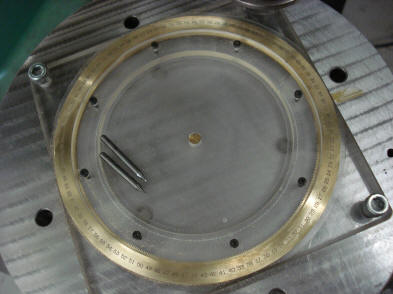
Deryck is using his numerically controlled dividing head, rather than
manually dividing the ring sectors due to the large number of divisions.
However, just to be sure he first scribed the left and right edges of the
dial aperture on the ring for each of the 100 positions as they click into
place as double check to the index. Of course for all of this to work, all
of the wheel works, and especially the feed ratchet, must be near perfect
for the entire system to work properly. The next photo shows the jig used to
hold the ring in position on the indexing head. All of this is custom made
for just this one ring.
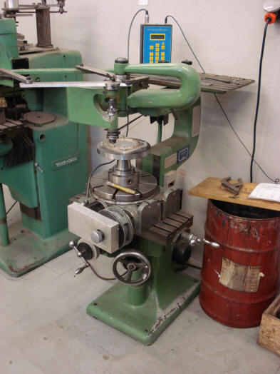
Just above the ring is
the engraving head of the pantograph engraving machine, first photo.
Next we see an overview of the pantograph
machine. The third photo is a close up of the letter-tray containing the
number masters. That tray can be seen behind the upper arm of the machine
holding the blue numerical index controller in the prior photo. That
controller is attached to the stepper motor which is attached to the
dividing head assembly, (the silver rectangular device). The entire indexing
system is attached to the bed of the pantograph machine. What we have here
is a combination of two machine tools to achieve an unconventional result.
Normally, a pantograph is used to create conventionally configured script
which is linear. In this case we need to engrave in a circular and very
accurate pattern, hence the need for this unconventional setup using the
dividing head.
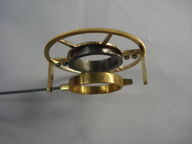
The first photo shows the pair of slotted angle brackets or ‘dogs’ attached to the center input drive wheel which in turn powers the zodiac precession and annual year indications. The next two have the rotating collet ring to which the planet Mars is attached via the wire shown positioned near one of the slotted brackets.
The center wheel
complete with brackets mounted in place.
The drive assembly is complete with both the
Mars planet attachment rod and its opposite planetary sign rod positioned
within the slots, see circled areas, second photo. It is this planet at the
top of the collet nest which is the input power to drive the center wheel
for our two complications. The wheels needed for these complications are
located below the tellurian deck which precluded the option of getting the
power feed from what would otherwise be the obvious point, the tellurian
rotating boom which rotates at once per year, but is above the dial and its
supporting structure.
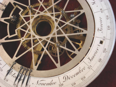
The entire mechanical
restoration of the year indication and zodiac precession is now complete.
The toothed ring that drives the lower silvered zodiac band is machined to
such accuracy that it can be held by the zodiac band by friction fit. The
view from ‘below the deck’ of the tellurian assembly is stunning. Compare
this to a similar view of the same area of the tellurian as received.
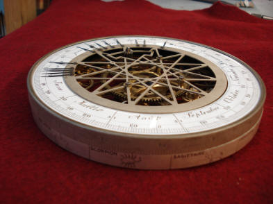
On the other hand, the
restored components are hidden from a side or nearly any other view one
might have of the clock. One needs to look carefully and deliberately to see
any of the components. The exception, of course is the fact that now we have
a functioning year indicator operating in the place where before we had a
blocked dial aperture.
|