|
Maker, Ferdinand Berthoud, Paris, France, c. 1785. Three train pinwheel escapement, 1/2 second gridiron compensated pendulum on knife edge suspension, 30 second Robin remontoire, full perpetual calendar, epicyclical equation of time, moon's age and phase, quarter strike on solar time Chime and strike can be silenced. 25.5"h x 12.25"w x 10.75"d, (65 x 31 x 27.5cm) Here we examine the the Robin remontoire of the clock. This type of remontoire may have been invented by Robert Robin of France. (1) In 1772 he presented a paper to the Academie Royale de Sciences on his remontoire for which he is best known. It is based upon the Christiaan Huygens endless rope system invented by Huygens in 1658 as means for maintaining power to a clock mechanism while it is being wound (an early type of maintaining power system), see right diagram at the end of this page. Robin's innovation was to make this endless rope maintaining power system automatic through one of the wheels in the Huygens system being powered by the main going barrel and released periodically by a detent, connected to the Huygens remontoire weight. This relatively simple, reliable system allowed a clock to have the portability of a spring-driven clock with the constant power of a weight driven clock. It also serves the same purpose as any other train remontoire of isolating the escapement from the inaccuracies found through the rest of the clock train.
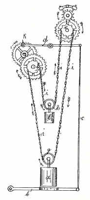
The smooth edged wheel mounted to the side of the clock and at right angle to the rest of the rest of the wheel works serves as a fly fan would in many other types of remontoire applications. It mediates the speed at which the remontoire is rewound. In fact a small oval conventional fly fan for the hour strike train is visible just below the horizontal frame pillar below the remontoire flywheel. The ornately spoked wheel mounted in this fashion was favored by French makers with other examples by Lepine and Le Roy. The rope line used in this type of remontoire is clearly seen just behind the main front clock frames. This is the only clock I've seen equipped with this type of remontoire that has the rope line installed between the clock plates. Normally the drive and pulley wheels are located outside the clock frames, usually on the rear side. This enables easy replacement of the rope in the case of wear and breakage. I cannot fathom why Berthoud made the servicing of this component impossible without disassembly of what is a very complex and difficult mechanism. Perhaps the original was a metal chain, rather than a fiber cord, but even so, this is a poor design choice and when one looks carefully at the mechanism could have been moved to the outside of the rear plate without much difficulty.
One can see the flywheel stop pins at the twelve and six o'clock positions. The latter being held by the remontoire detent. That detent moves slowly inwards until it allows the small pin to slip past and returns before the wheel makes its 180 degree turn, thus locking that wheel until the next cycle in 30 seconds time.
A helical toothed wheel drives a worm gear cut from the remontoire fly wheel arbor. In this way the fly wheel can be mounted transversely to the rest of the mechanism.
Here we see both a close up of the rope and drive pulley as well as a beautifully fretted cock supporting the rear end of the remontoire flywheel pivot.
Another view of the intersection of the flywheel work and helical drive wheel. Note the complicated corner shaped piece that serves as the from pivot support. This also has an adjustment piece allowing for proper depthing of the worm to its drive wheel, see first photo.
This is the smaller tensioning pulley that serves to keep the rope just tight enough around the pulley wheels so as to prevent it from derailing.
|


![]()
![]()
![]()
(1) There is a diagram by Huygens from 1663 that describes this same remontoire principal, although it does not appear that he applied for a patent or ever actually built a prototype. The Evolution of Clockwork, Drummond J. Robertson, pp. 151-158.
Continental and American Skeleton Clocks, Derek Roberts, p. 24