Continue strike hammer linkages - February 2014
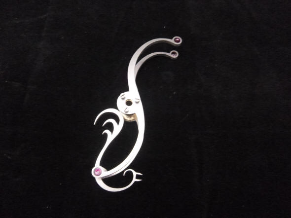
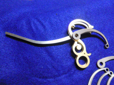
The first photo shows a completed lower hammer impulse lever assembly less the jewelling for the bird's beak. Next this is mounted into the clock to check for fit.
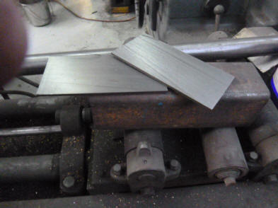
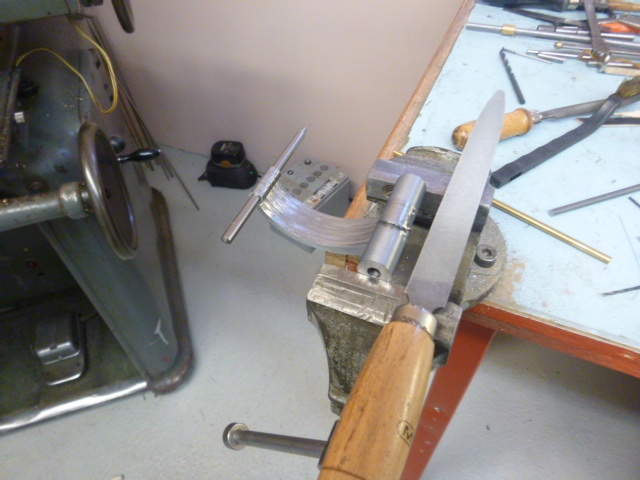
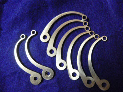
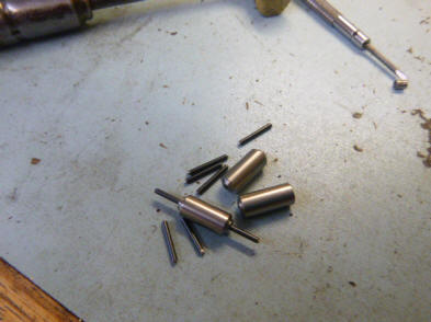
The first photo shows the steel blank used to create the following linkages. Since these will eventually be blued the metal is made from standard carbon steel material as opposed to the stainless used for all of the arbors. Next we see a set of levers all aligned together so when Buchanan files these to the desired shape they all are uniform.
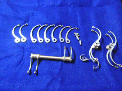
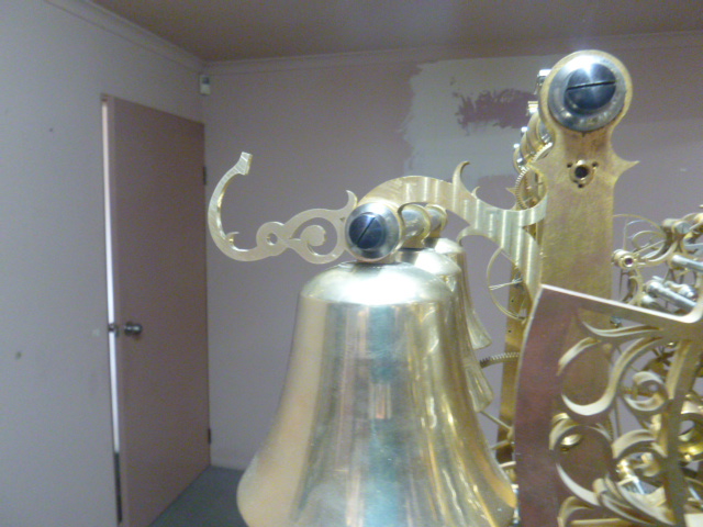
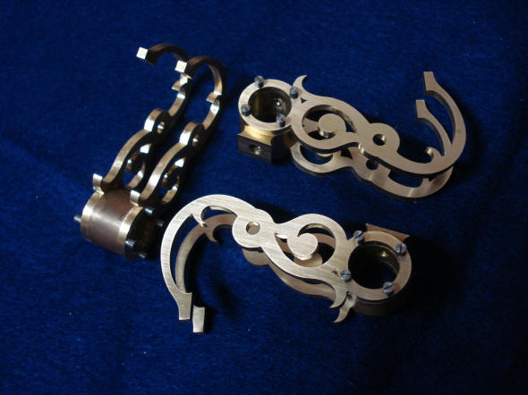
As with most everything else in this project there are a myriad of parts specified where a fraction of those would be called for in a conventional design. The third photo shows the curvilinear lever and hammer stop support brackets that compliment the same designs used elsewhere in the movement. The fourth photo shows how this new bracket seems to be an extension of and grow organically out from the strike pillar. The build out of these components now begins to take shape.
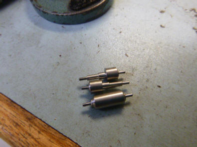
In this series of
photos Buchanan is making the small stainless steel arbors upon which the
impulse levers, the roosters, will be attached.
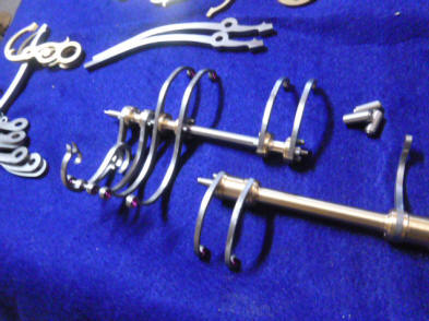
The completed impulse
levers are now installed within the clock movement. The remaining linkages
have yet to be connected.
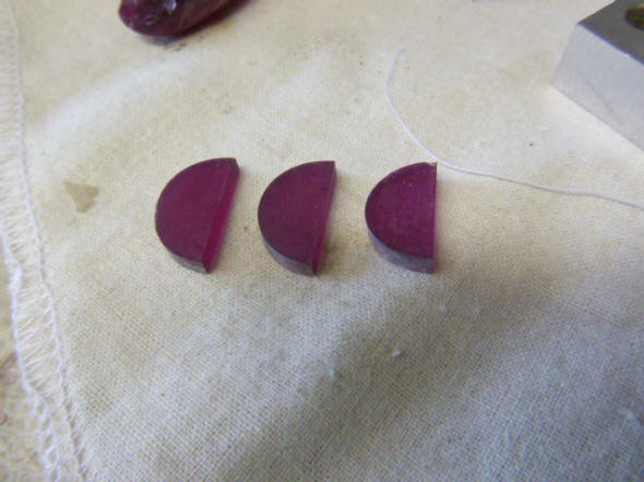
Buchanan now begins to
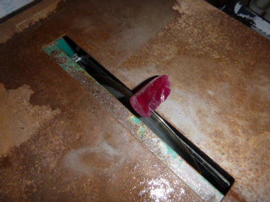
make the jewels for the rooster’s beaks. The beak is what contacts the
impulse bar on the strike train carousel to give lift for the hammers. First
the rough boule is sliced into three pieces, one for each rooster’s beak.
The half discs are then mounted to the armature which is part of the shaping
and polishing machine that will create the final jewel’s shape and finish.
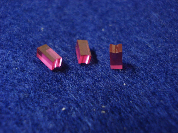
The finished jewels ready for mounting.
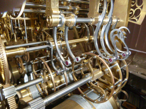
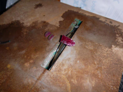
The jewel beak is mounted into the rooster hammer impulse lever set upon the
carousel cam drive wheel. Note the jeweled pivots used through this system.
This design is quite different from most
conventional strike cam/lever systems. Usually there is a fairly long
sliding surface where the cam rides along the lifting lever to raise the
bell hammer via a wire rope or rod. Here we have the lifting lever meeting
the cam rung at a single point. The rooster beak rotates about 300
upon the carrousel cam as the carousel wheel rotates counterclockwise (as
seen from the rear in these photos) thus pushing the rooster lever upward to
raise the hammer through the remaining compound lever system.
The upper lever and hammer stop support units are assembled. The cheese head screws will later be changed to a countersunk oval head style.
|