|
Dial hands finished, sedan chair carry frame constructed, debugging begins - February 2021 This month Buchanan finishes the world time and tellurion zodiac house indicators, swaps out the incorrect season dial for a remade one. Then the sedan chair carry frame is redesigned and constructed. This will be used in the transport of the clock. Debugging of the machine begins.
This photo is from a
clock I saw in the French magazine Horlogerie Ancienne,
no. 40, 1996 as an idea for the world time dial early on in the project. It
has the advantage of having numerous cities listed, one for each of
twenty-four hours, many of these are not well known, but I suspect are all
neatly one hour apart. My idea was to make such a dial out of glass in order
to still allow one to see the mechanism behind the dial. Buchanan suggested
our dial was too small to make this legible and wanted to try to find a
maximum of eight major cities spread out over the twenty four hour dial.
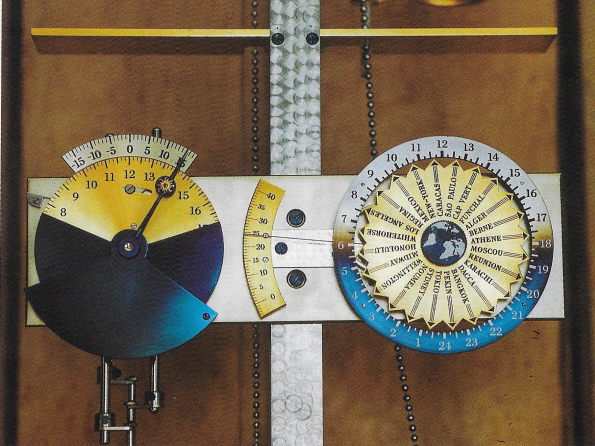
Buchanan provided a
time zone map to show where various cities are located within the time
zones. The point of this is to try and find not only the cities we wish to
portray, but their locations which need to be somewhat equidistant from each
other, otherwise they will be too crowded to be easily read. One must
remember that the entire dial is under two inches (5cm) in diameter.
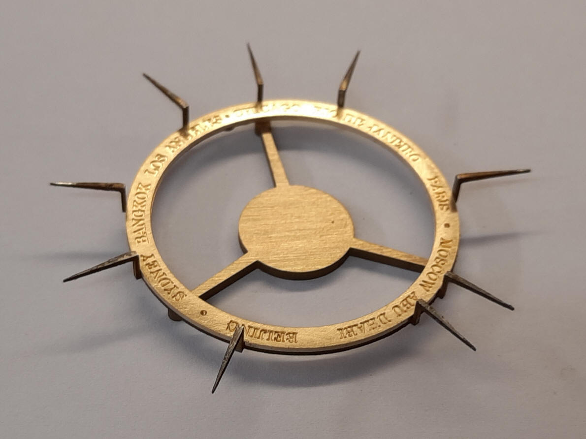
Buchanan's first concept is the illustration on the left. It still bears some resemblance to mockup dial that was still in place on the clock with arrows for each city. The second drawing refines the concept, integrating the now nine cities dial ring and the indicator hands located outside the ring.
The first photo shows Buchanan's wire erosion machine cutting out the dial indicator ring, the part that has all the dial hands.
The nine cities uses the same Century font as was for the Latin inscription around the planisphere dial.
The main parts of the dial.
The parts are now assembled. The reason for the strange angle of the dial pointers will soon become apparent.
The dial is now silvered, with black waxed lettering and finished hub.
The time hand assembly is now inserted into the existing twenty-four hour enamel dial. Now the reason for the articulated hands becomes apparent since these along with the cities name ring is countersunk so as to be flush with the enamel dial. The winding square in the center serves as the celestial demonstration key crank. I found the design for creating the this dial to be quite special because the enamel twenty-four hour dial was already made and the concept for the display of the cities was not firmly conceptualized until now. Buchanan was able to make a useful and visually beautiful solution on an ad hoc basis working with and around with what was already fabricated. This talent has been demonstrated time and again in this project.
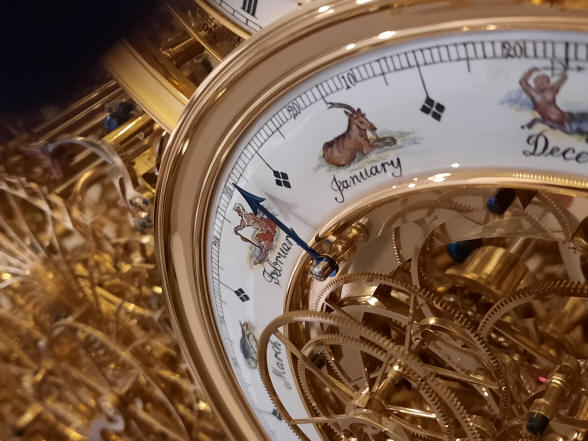
The zodiac house designation dial hand is attached to the center of the tellurion counterweight, opposite the Earth. This shows the position of the Sun as it appears to travel though the sky relative to the designated houses of the zodiac illustrated on the dial. This is, of course, simply an apparent movement caused by what an observer sees from the face of the Earth as it orbits the Sun. That same positional information is reflected in the planisphere dial in a more realistic way by actually showing the star field as seen from Earth with the Sun shown against that field and the twelve zodiac houses outlined by various star configurations.
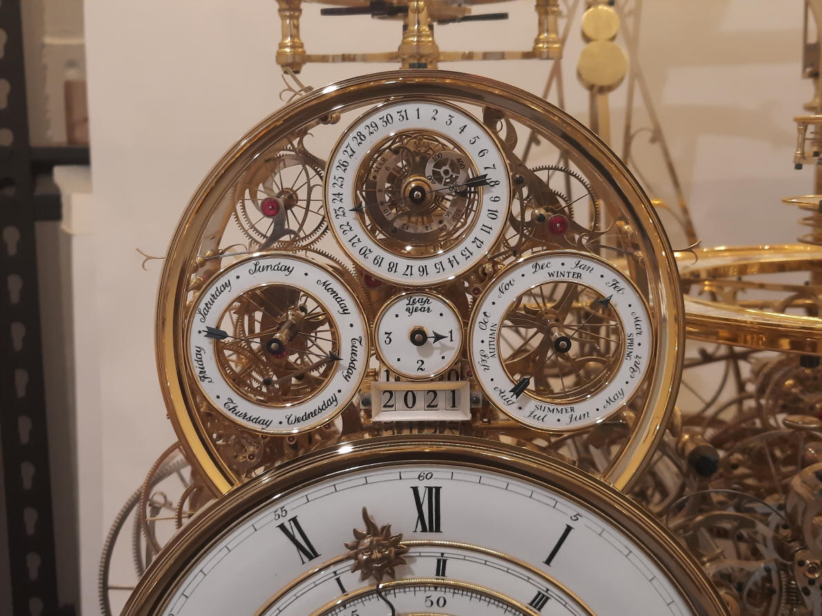
The original dial, right had a mismatch between the season and the months. Summer appears below December and January. Where the clock is now this would be correct, but for where it will reside on the opposite side of the world the new dial, left is needed. Buchanan needed to open up the inner diameter a bit to fit the bezel which has already been made for the current dial, second photo. Fortunately we were able to source the same artisans in China so the background white and lettering style remained consistent. The original dial was completed in June 2013.
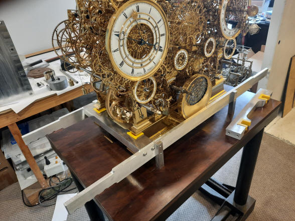
The new dial within the calendar module. Buchanan now turns to the redesign and construction of the carry frame which he has named the Carry Frame Mk2. I have often referred to it as the sedan chair since the clock within the carry frame will be carried just as a person would sitting in a sedan chair.
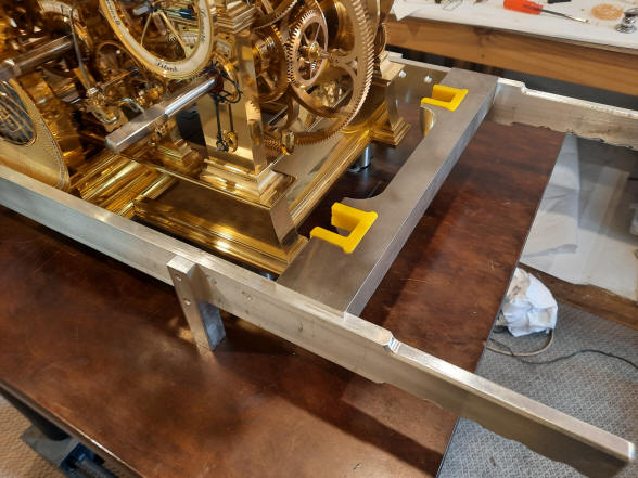
The first photo shows one of the rubber protective inserts. The second photo shows the part fitted to an aluminum block to test the fit.
The aluminum block has now been milled to the correct outline, next shown laying across the two main rails of the carry frame.
The completed carry frame.
Left photo, a view with carry frame attachment slid into position, right a view with the attachment yet to be inserted into position.
The carry frame is now attached to the clock, and now takes on the character of a sedan chair. Notice how this photo accentuates the tapered look of the machine.
This redesign is a significant improvement for two
reasons. First, the pendulums do not have to be removed to move the machine.
Removing the pendulums is tricky and requires the removal of several other
systems. In fact the new design even allows for the planisphere in the front
to remain, so the only item that needs removal are the lower balance ball
weights; the balances will be locked together with a jig held below the
upper ball weights during this time. This scenario will be needed to move
the machine from the initial temporary table to the final table once it is
constructed and is expected to be a very short lift from table to table. The
permanent table will not be made until I determine the ideal height for the
clock and case. For the initial delivery the same carry frame will be used
without any of the pendulums or complications mounted. Second, the carry frame is attached directly to the
main frame rails and not the winding barrel arbors. This precludes the
possibility of damage occurring between the barrel pillars and the main
frame since the barrel arbors are mounted through the four pairs of frame
pillars which are in turn attached to the main frame rails. Though unlikely,
movement could occur between these pillar parts the pair of front and rear
main frame rails as well as between the barrel arbors and pillars. The carry frame is made stiff enough to preclude any racking should there not be an equal lift from corner to corner of the frame’s handles. Buchanan now turns to the debugging of the machine. As can be imagined with over 7500 parts of which over 1000 are movable and hundreds of others that are critically positioned for the machine to function, this will require meticulous investigation. Buchanan
writes:
Just an update on debugging.
One of the pawls on the 1/4 sickle lever has been temperamental, I found a
counter balance weight (tail feathers) was not properly positioned. I had
not set it when polishing and slipped up in not remembering to set it when
assembling the clock.
I fixed a loose clamp on a balance diagonal. Not enough clearance in the
clamping slot. Set the calendar hands dial to hand clearances, the hands were too far from the dials.
Fine-tuned the strike levers and set up the cams on the sunrise set times,
they were operational but not properly adjusted.
I have one squeaky mainspring when winding, nor sure why, this is next,
The two final drive gears below Saturn and Jupiter do not align with the
large idler gears so I am going to fix that. You can see it in the orrery
photos attached, see below.
I reply:
Better that you catch the bugs, they’d all run away too fast from me to
catch! Thanks.
The Robin remontoire upper pulley and overrun clutch assembly removed for debugging a rattling assembly.
This photo shows the misalignment of the drive wheel to the Saturn model and its drive armature. Further debugging will be done in the next installment. |


![]()
![]()
![]()