|
The analog thermometer - March 2017 This month Buchanan takes a break from the Sun / Moon complication to fabricate the only non-horological feature in the astronomical clock, a thermometer. A thermometer is not so unusual within the context of clockwork. Many precision clocks from the late 16th century on had compensated pendulums that contained a temperature indicator near the pendulum bob to give the viewer a sense of the changes taking place within the (usually gridiron) compensated pendulum. These were not true thermometers reading the actual temperature, but indicators of the changes in the length of the pendulum rod roughly corresponding to a rise or fall in temperature. A few pendulums had actual analog thermometers incorporated into the pendulum bob. And later precision laboratory and observatory clocks had thermometers to help rate the clocks.
Buchanan
sent me these two photos and wrote:
On Monday I will start the thermometer. Are we thinking a mercury? See
attached Photo (first photo) , or mechanical? (second) The mercury would be
cheaper!
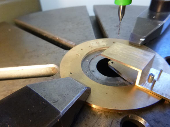
The first photo shows the raw stock, grade 316 stainless steel, which will comprise one of a
pair of concentric rings that will eventually form a bi-metallic compensation ring. Next
the steel ring is shown cut out of the stock. The ring with the multiple screws
in the background photo is
the bi-metallic compensator,
and is the way such bi-metallic strips were made before a method of fusing
the steel and brass was employed.
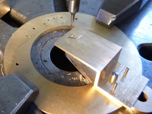
The first photo shows the beginnings of the second, inner brass ring, next a
few of the forty screws which will eventually secure the two together. In
the upper left hand corner one can see the steel ring tightly positioned
around the inner brass ring.
The forty screws securing the bi-metallic compensation ring are now in
place, simply beautiful.
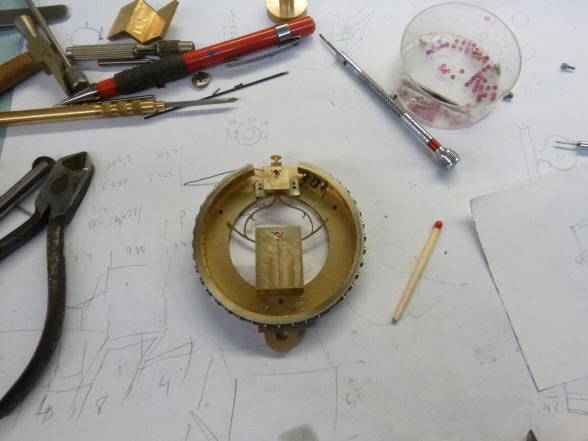
This block contains parts that will mount to the sector gear and lets it adjust the sensitivity of the thermometer. A piece of fusee chain connects the bimetal ring to the curved section and by sliding it in or out and this allows a change to the leverage ratio.
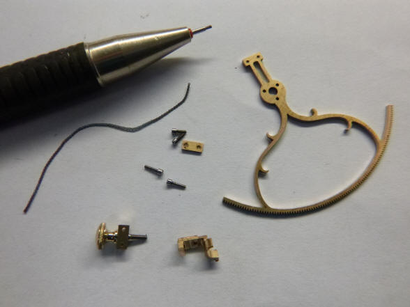
The various components
of the thermometer excluding the case, bi-metallic ring and dial readout.
The first photo shows
another batch of twenty screws made for the thermometer, 0.6mm (24
thousandth of an inch) diameter, 0.15mm pitch. Next the screw slotting jig;
a clever and simple design by Lindsey Drabsch of Canberra.
Now the front cock
blank for the dial hand is secured to the rear plate. Next the drilling of
the center hole and three surrounding screw holes to secure a jeweled chaton
for the center dial hand.
Here the bridge blank is drilled for
the sector gear chaton, next the holes for the two chatons located on the
rear plate are drilled.
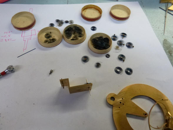
The first photo shows the sector gear bridge with the associated parts that will comprise the four jeweled chatons for this assembly. Next the parts are staged before chaton insertion.
In the first photo the
chatons are installed and next the sector gear is installed.
The first photo again
shows the small scale we are dealing with within this assembly. Next a view
of the knurl knob used to actuate the fine dial adjustment.
These two photos show
the gross adjustable link to the fusee chain. Once the thermometer is rated
within a reasonable tolerance, the gross adjustment link attached to the
fusee chain is locked down to the post connected to the bi-metallic ring.
The first photo shows the link assembled. Next the link is removed from the
post. Even at this small scale and a part that would never be normally seen,
a small decorative spur is made on the post.
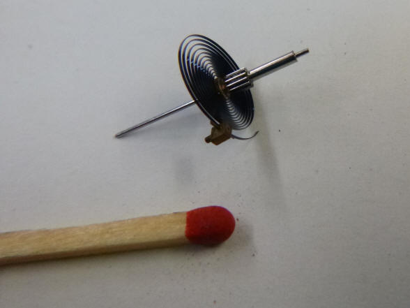
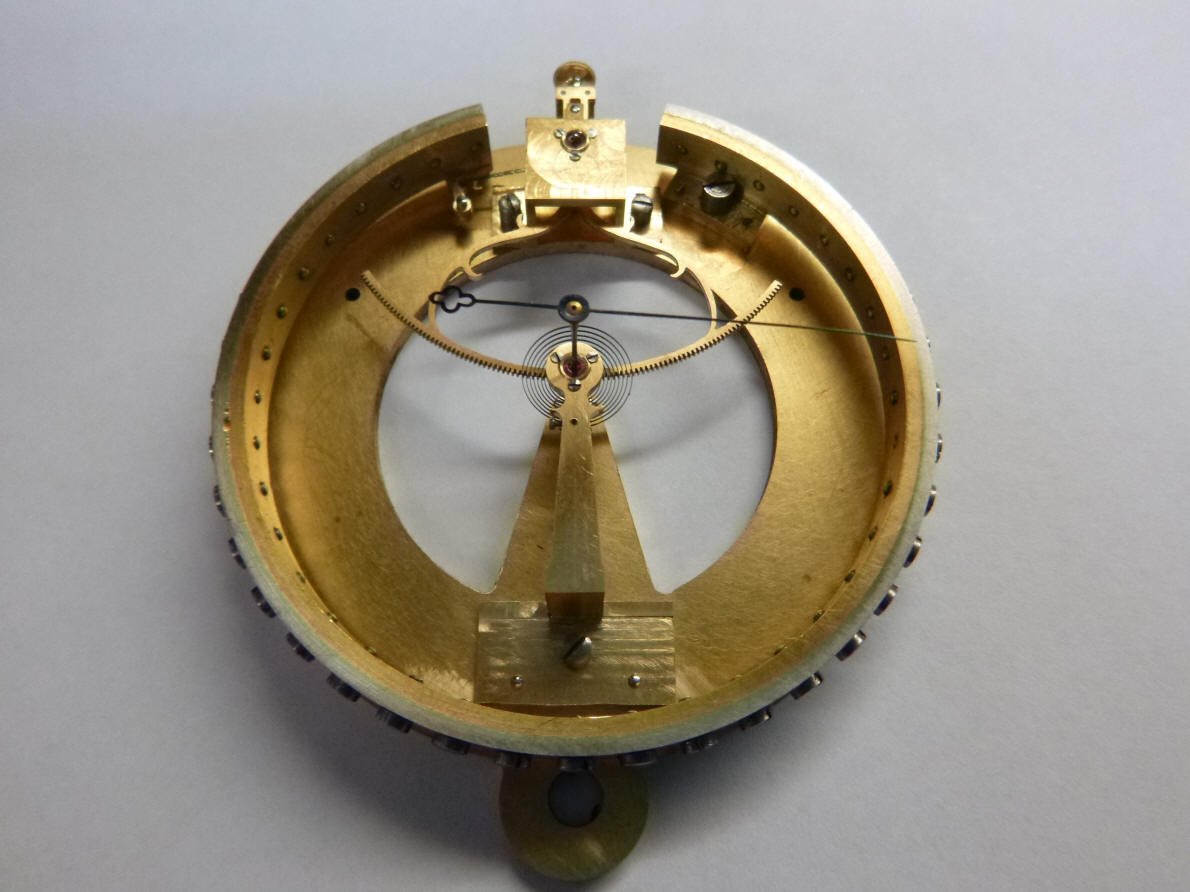
An anti-lash spring is
chosen from inventory. This device is needed to eliminate any wiggle on the
readout hand. Everything is at such a small scale that any lash between the
sector gear and the dial pinion is greatly magnified by the very long hand.
Next the dial hand pinion is cut and pinned to the spring.
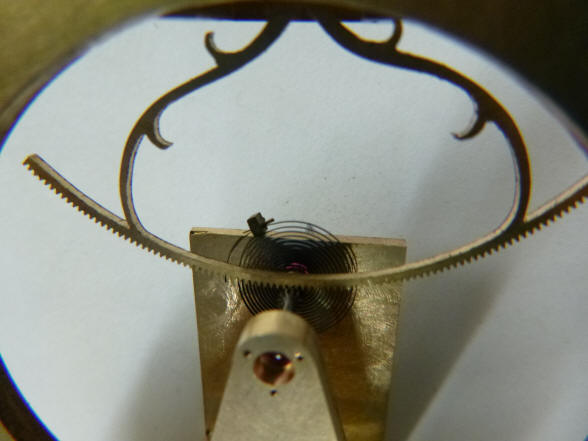
The spring is about the
size of a pocket watch balance wheel hairspring. The spring and pinion are
next fitted into the dial cock to check for fit, the cock in the background
must first be cut to the final decorative shape before the spring can be
pinned to that part.
Photos of the completed
thermometer. There will still be further skeletonizing and refinements to
the components. The instrument must later be calibrated before the dial
artwork can be made for the eventual enamel dialing later on.
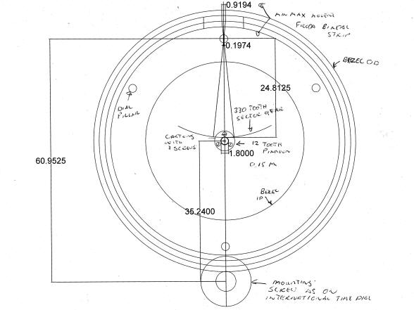
The first photo shows a
rough mockup for the thermometer dial and bezel. The dial is completely
wrong as we had figured that a different function would be in the
thermometer’s location. However, the dial size is correct as well as the
bezel. It is a bit of a shame that much of the beautiful bi-metallic strip
screws are hidden as well as most of the rest of the mechanism behind the
dial, but this was unavoidable as this particular device has nearly all of
its mechanism around the perimeter. One will simply have to look around the
corners a bit. The second photo shows the thermometer along with the
temperature calibrator. Note the alcohol glass thermometer as a secondary
check. It is unknown at this
time how linear the thermometer will operate. Once the calibration is
performed the dial artwork will conform to the actual function. |


![]()
![]()
![]()