Strike and repeat control assemblies, quarter rack lifting and gathering pawls; rack let down flies - June 2011
This month we continue with the fabrication of the strike train control systems and now proceed with the rack lifting and gathering pawls and the rack let down fly fans. In a conventional rack and snail strike system the rack is raised by a single or dual toothed pinion, and an accompanying pawl holds the rack steady at the newly raised level after each engagement of the pinion. The rack continues to be raised in this manner until the strike sequence is completed. We have chosen a more interesting road. In our movement the role of the raising of the rack and its holding during the strike sequence is performed by a seesaw performing both of these functions. I had first seen this in the ecclesiastical computer contained within the cathedral clock built by Jean-Baptiste Schwilgue in Strasbourg, France, c. 1843. This is another example of my borrowing an ingenious design from the masters of horology and incorporating it into this project. We have done this with earlier components starting with John Harrison's visually impressive dual compound pendulums driving his equally inspiring grasshopper escapements. The remontoire powering those escapements are Bernard-Henri Wagner's swinging frame remontoire; a particularly stunning example of differential gearing, along with Robert Robin's beautiful chain drive remontoire for the accurate release of the celestial train's functions. Also Tompion's differential system to read the equation of time directly from the mean solar time dial is employed as an alternative to the simpler sector dial arrangement. There are more examples to come. Buchanan says that we are now entering a difficult phase of fabrication. Up to this point the lion's share of the movement, excepting the frame, was the fabrication of wheel works. Making wheels, according to Buchanan is straight forward. Once one establishes the wheel and pinion counts and modules, the wheel's characteristics are determined. The diameter determines where the wheel will be planted with regards to its neighbors and from this the locations of the wheel pivots. Here we are creating lever, rack and interconnecting assemblies that will need to be made to conform to specifications in all three dimensions. Any change in one component affects all of the others. Lengths, angles as well as visual esthetics must all be considered in unison. Concepts must first be drawn out, then initially fabricated in wood or plastic to test their viability and then either tested again in brass or cut directly to the final steel material. This material will later be polished and blued.
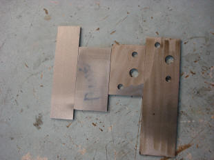
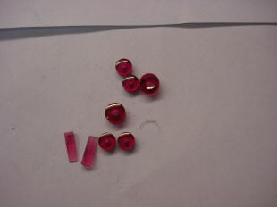
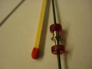
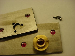
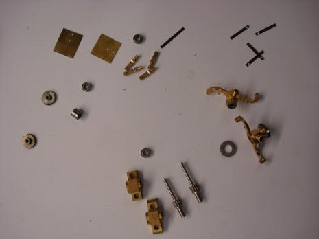
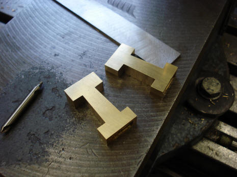
We now begin the quarter strike lift and gathering pawl rocker assembly. The first row of photos show the raw stock with the outline of the rocker frame drawn on the surface. Holes are drilled to accept the pivot jewelling. Next the jewels are assembled. The flat jewelling is made in-house. The middle photo shows one of the parts that serve both as a spacer between the rocker plates as well as a pivot for one of the pawls. The last photo shows the two pair of pivot jewels which will later support our allegorical bird pawls. The center chaton is the pivot upon which the entire rocking pawl assembly is mounted. It is double-flanged and is the structure that holds the two parallel rocker plates between which the two pawls are pivoted.
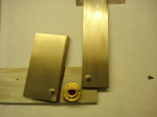
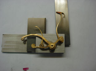
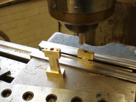
Next the vertical base stock for the bird pawls is fitted. The second photo shows the outer rocker plate set on top of the two vertical pieces. The last photo shows the plastic mockup which was made to test the working concept set upon the raw steel stock as a final check that its dimensions are incorporated within the entire material available.
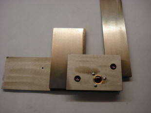
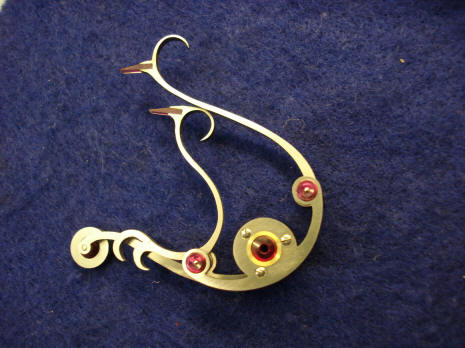
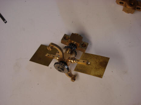
The assembly is then fitted to the arbor upon which it will be supported. Now the exact positions for the jeweled beaks of our birds can be determined in relation to the teeth of the rack. The flat jewelling representing our bird beaks are next fitted to the steel stock and tested for fit and functionality.
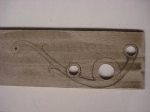
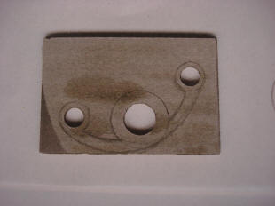
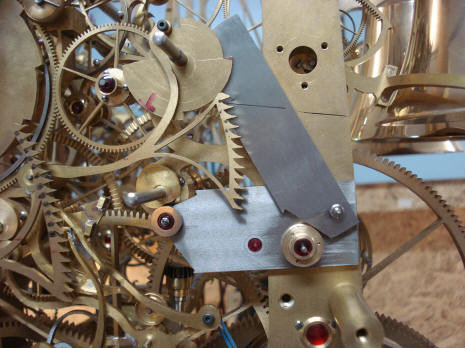
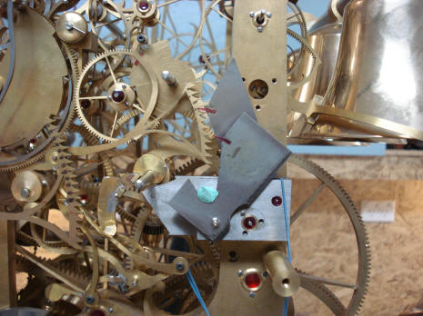
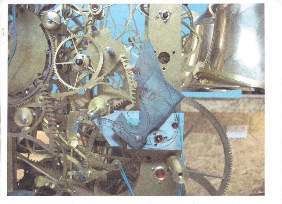
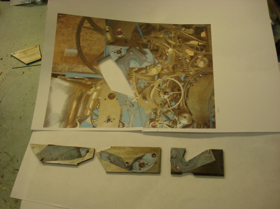
The design of the pawls as represented by the plastic mockup were never meant to be the final shape. That mockup was used to test the design's functionality. To create the final design Buchanan first began by drawing his concept on a photograph of the actual parts mounted to the movement. These drawings flow over several layers of parts as shown in the picture above.
That picture was then carefully cut up and these were used as templates to cut the outlines of the metal pieces. The size of the photocopy had to be carefully calibrated to match the actual dimensions of the real components. One can begin to see the labor intensive nature of this part of the project.
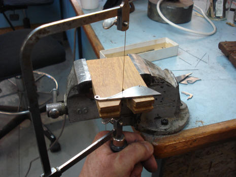
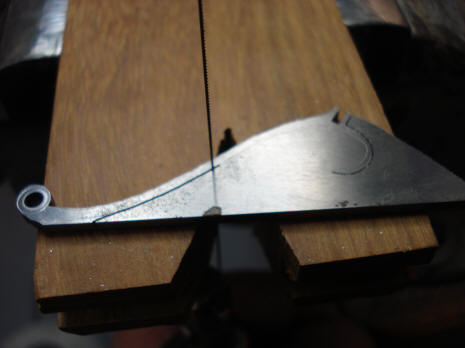
The steel components are cut by hand. The electrically powered jeweler's fret saw used for most of the brass flat stock in this project is not suited to cutting steel stock of this thickness and a larger machine would not afford the delicate pattern that we want to achieve. This sort of hand work will give the project an 18th century feel. What I call a 'warmth' to the project that simply cannot be had from a computer aided manufacturing process.
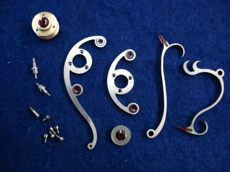
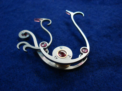
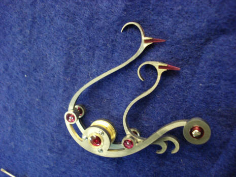
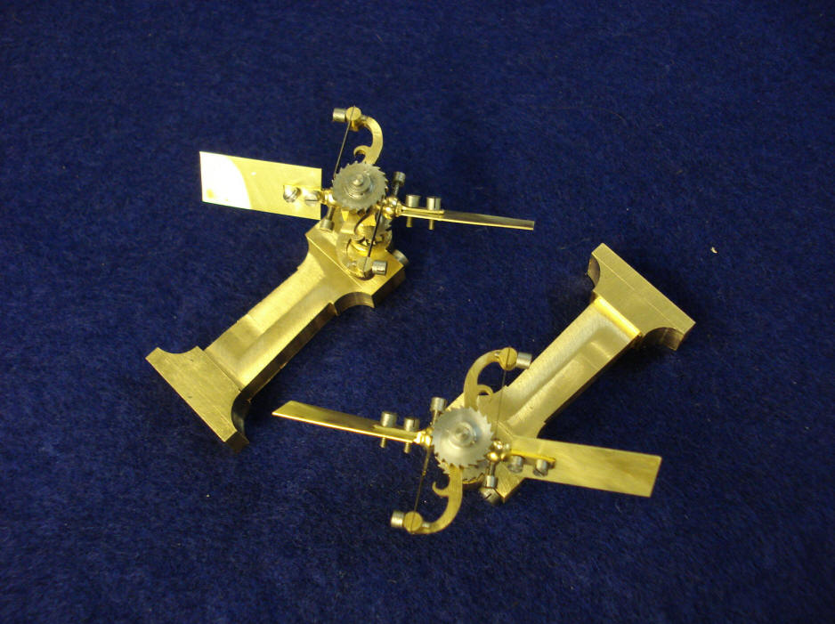
The final product is shown above. In a conventional system one would have between the rack pinion and gathering pawl maybe a half-dozen components. Here we have twenty five.
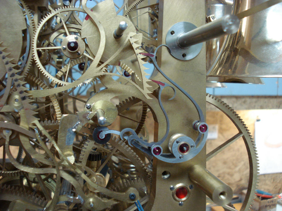
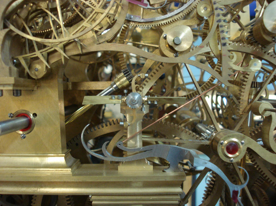
The final assembly is mounted. The biasing spring is not yet shown. Look at the very far left of the assembly to see the wheel which by rolling against the heart-shaped cam, (later to be skeletonized), will induce the back and forth movement to the rocking pawl assembly, see videos below. Under conventional design standards that cam would have been the single or double bladed pinion that would have been positioned next to the rim of the rack teeth with a simple pawl to hold that rack during striking.
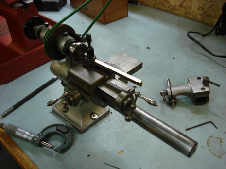
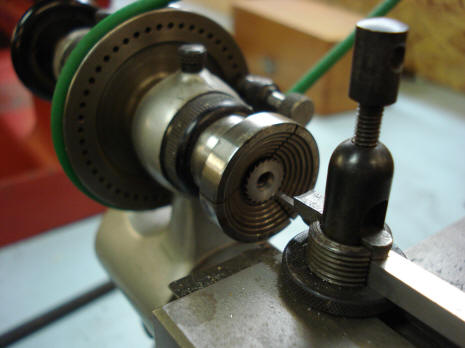
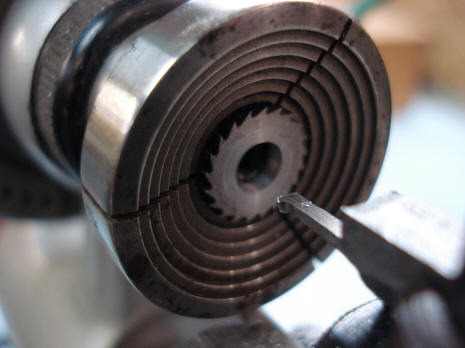
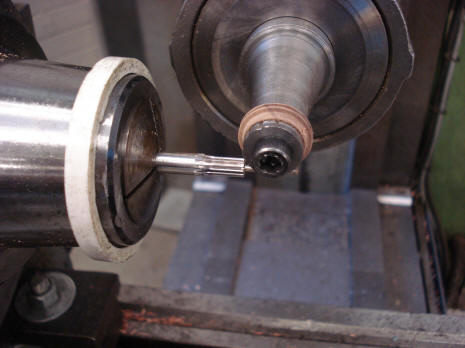
We now begin the fabrication of the quarter and hour rack let down flies. These will mediate the fall of the quarter and hour strike racks. While not completely necessary, the racks are fairly large and their tails will fall onto the thin rims of the skeletonized snail cams, and besides it gives us another opportunity to introduce another eye-catching feature to the mechanism! These four photos show Buchanan trimming material from the inner opening of the let down fly ratchet wheels. These parts are small enough to employ a watch lathe. The scale of the parts we will be making, in most cases, from now on will be on this order as we move on to the various complications.
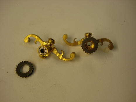
The first photo shows the exploded view of the fly fan pair; approximately 32 parts. Next the rough-assembled fan. The third photo shows Buchanan polishing the pinion teeth with a wood blank charged with polishing compound that has the exact tooth profile milled into its surface. All pinion teeth are polished in this way. The last photo shows the beginnings of the fly fan pillar mounts.
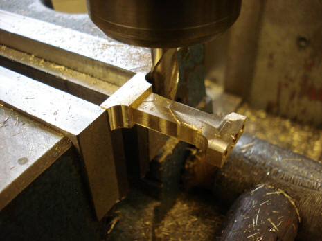
Next are some of the various machining steps necessary to create the pillars.
The fly fans are now mounted their pillars. These are still far from finished. There are a lot more refinements to be made to the pillars as well as the fly blades. The screws holding the fly blades will be trimmed to size and the heads made smaller to be better proportioned.
These photos show the fly fans mounted within the movement. We now have the ability to set the quarter strike train in motion. The videos below show the initial tests before the completion of the fly let down fans. The quarter strike rack simply falls in the conventional manner via gravity without the let down fly fan's assist.
Astro_06-11_vid1 Astro_06-11_vid2 Astro_06-11_vid3 For those who cannot use the built-in viewer above, I have added the YouTube viewers below. You can also click on the individual video links above and a clip will open on your computer's built in video viewer. https://www.youtube.com/watch?feature=player_embedded&v=fY2hxUfbHKQ#t=0 https://www.youtube.com/watch?v=VsFhFn-0Wpw&feature=player_embedded#t=0 https://www.youtube.com/watch?v=2Z_R-5CNAk8&feature=player_embedded#t=0
|