Continue Robin remontoire - July 2009
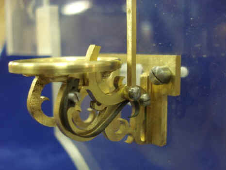
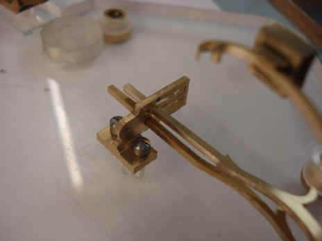
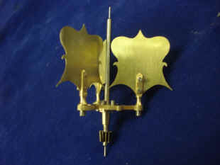
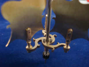
This month B. continues to fabricate the Robin remontoire. First he begins with the weight pad. This device is pivoted and attached to a lever. When the remontoire weight depresses the pad (third photo), the lever is moved and the remontoire cycles. Note the curvilinear design continues on this part (forth photo).
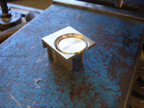
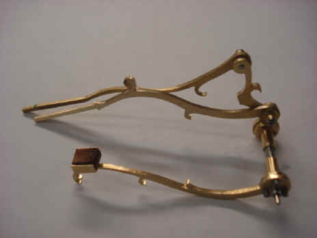
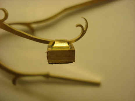
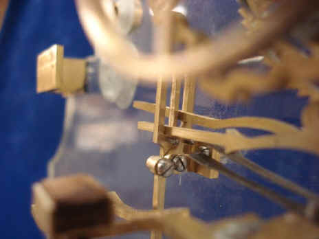
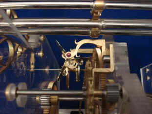
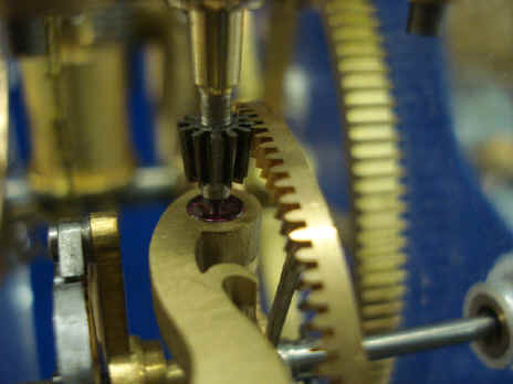
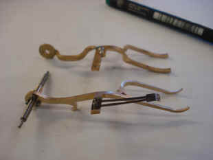
Next begins the fabrication of the complex set of levers to control the remontoire's action as well as the safety function in the event of a lock-up of the celestial train. The second photo shows the leather-surfaced brake that will engage the smooth disk (later to be skeletonized, in the event of the celestial train lock up. This will act as a sliding brake. Not to stop the mechanism but to bleed off some of the excess energy that would otherwise present itself to the time train in the event that this energy is no longer being used to drive the celestial train. Remember that we are using both weights for the time and celestial train in tandem to drive these trains because of the vast differences between the energy needed for the time verses the celestial train. In this way we can equalize the size of the weights needed between the two trains; avoiding an overly large weight needed for the time train. It is estimated that if the two trains were individually driven the weight needed for the time train would be about 165 LB (75 kg) and the celestial train about 20 LB (9 kg). Since these weights are both needed to drive the two trains, in the event of the celestial train's failure we must still allow the celestial train barrel to turn but deal with the excess energy. This is where the clutch comes in. The next two photos show the levers with emphasis on the last illustrating the beautiful fillip on the end of the clutch pad.
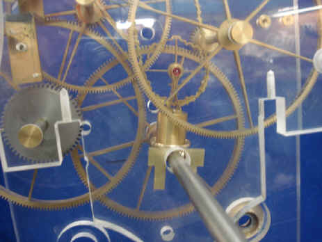
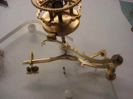
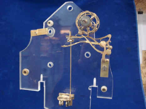
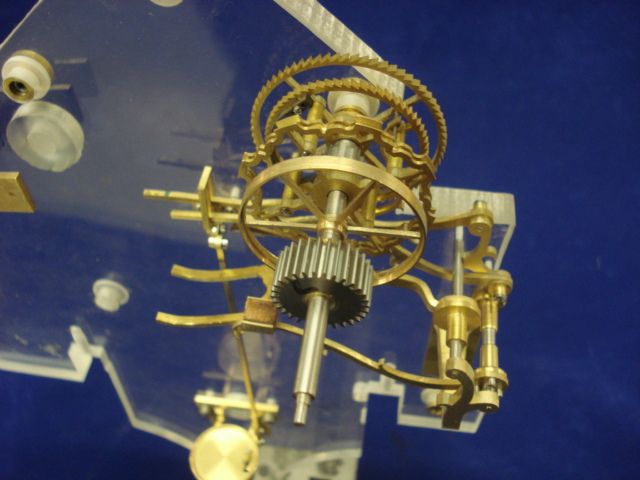
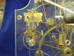
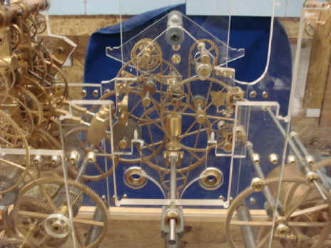
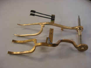
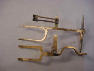
The first photo below shows the set of levers controlled by the weight pad which is shown near the bottom of the second photo. The third photo shows the clutch and its associated levers from above. The friction disk is now spoked out. The over wind fork shaped lever is still the prototype model. Fabrication of the actual part is shown at the end of this page.
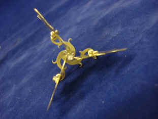
The three bladed fly is now fabricated. The design of the fly blades are in keeping with those of the Wagner time train remontoire. This fly, unlike those of the time train Wagner remontoire, is purposefully buried deep within the movement. I wanted it to be like a bird or butterfly 'caged' within the confines of the movement. It will operate on a different schedule than the time remontoire fly fans adding to the visual experience. More on this in the next month. The design of this small part illustrates the efforts we have put forth on the entire project; maintaining a consistency of style, complexity, movement and beauty.
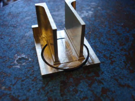
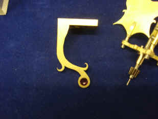
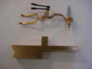
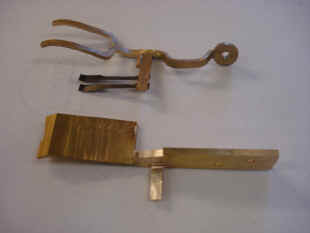
Below are a series of photos concerning the fabrication of the over wind lever. This is a fork which the remontoire chain and weight pass. In the event of the celestial train stopping the weight will rise above its normal height and raise this lever. This is a complex part in terms of three dimensions. So B. makes a prototype complete with rough solder connection and places it next to the solid block from which the final part will be fabricated (first photo). The rest of the photos show the generation of the part. This job is done largely by hand using saws and files. His prototype, with a bit of dressing of the solder connection, is of a quality many clock makers would consider their finished product. The final part is made of one piece, no soldering. This is one of the specs for this clock, no solder joints.
|