|
Continue Sun / Moon rise/ set, sun hand, glass dial work, redo center dial and bezel - August 2017
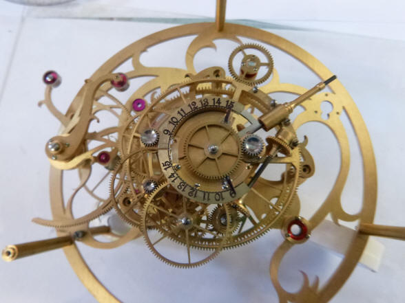
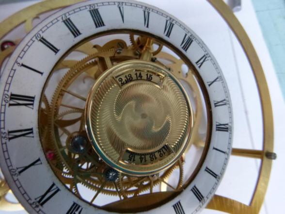
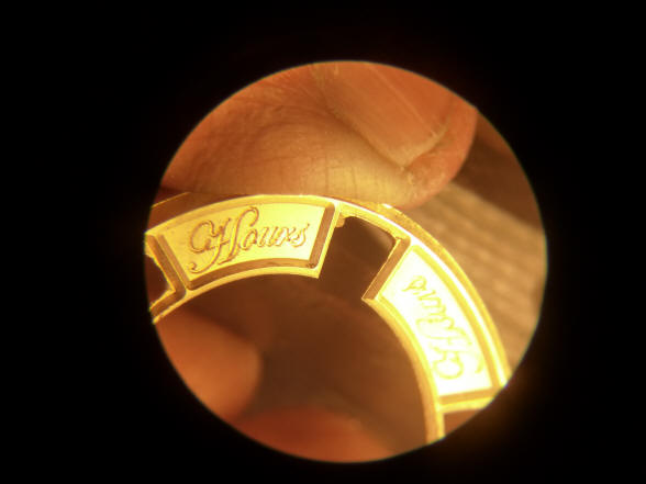
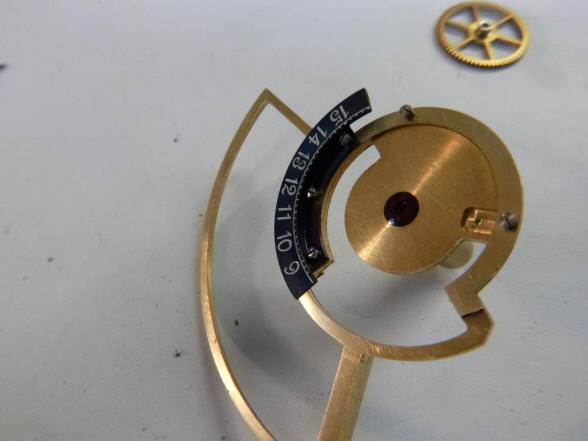
The first photo shows
the semi-finished hands for the center hub dial depicting the length of day
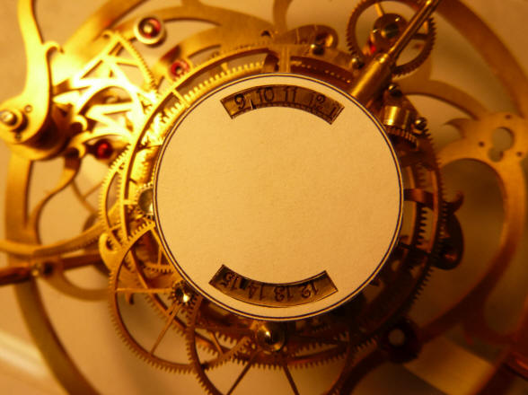
and night hours. The next photo shows the initial dial mask for these two
indicators. I will reserve judgment on this for now; it appears to be a big
blank cover, the opposite of what we try to do with trying to expose as much
of the machine as possible.
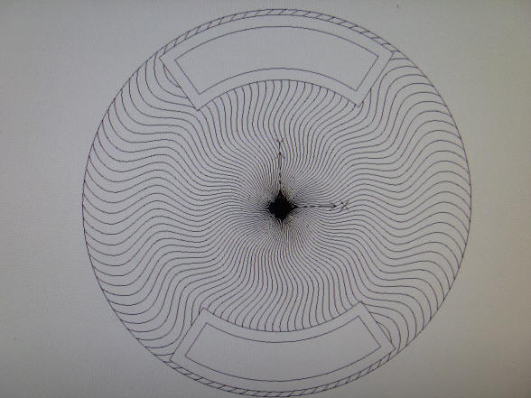
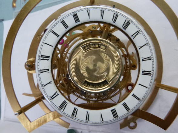
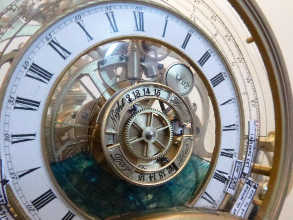
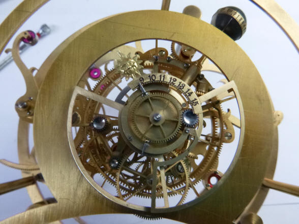
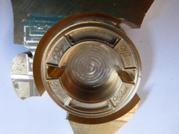
This is the first design concept for the
center dial within the sun/moonrise dial set. The first picture is a photo
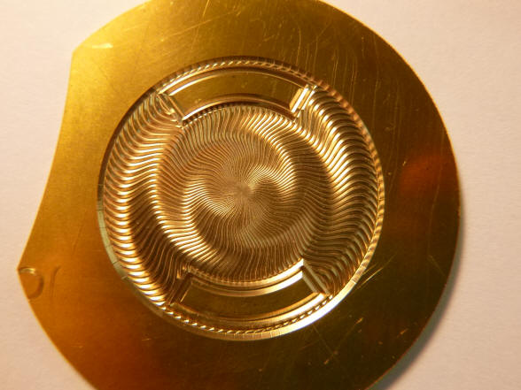
of the CNC design from the computer screen; next a proof-of-concept initial
brass engraving. Even though the pattern is beautiful, I want to steer away
from a central disk with two apertures for hours of day and hours of night
sector dials as shown here. I’d prefer that the two sector apertures be
‘floating’ in front of the numeral dials behind. This is in keeping with the
bezel we created for the digital readout of the year in the calendar dial
cluster.
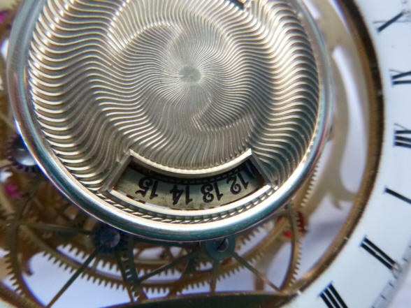
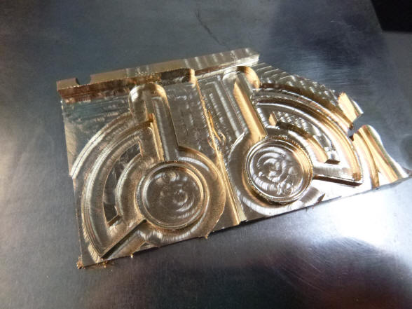
While the damascene machining is nice, there is still too much of the center covered.
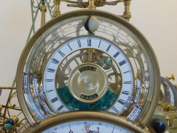
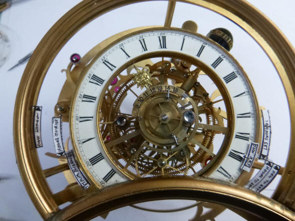
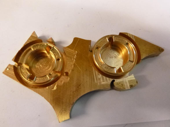
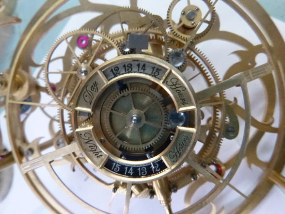
Here is a side by side
comparison. I know many people will like the fancy machined cover on the
left, but the dial on the right has the advantage of having space for the
labels and we have to this point always tried to show as much mechanism as
possible. Furthermore the numbered dial plaques also move in the opposite
direction to the dial pointers. This allows for a greater perceived sweep of
the hand over the dial than could be had with the dial pointers being driven
over a stationary dial. This clever artifice was necessary because the size
of the cams and their followers would not deliver enough movement to make
the hand sweep over the entire dial if it were stationary. With the open design one will more
readily see this arrangement.
We now turn to the
fabrication of the glass dial and horizon shutters. The dial specifications
call for very a thin glass of no more than 1.2 mm (0.047”) for the dial as
well as the shutters. To compare, the standard single strength window glass
in the US is 2.38 mm (3/32”). Buchanan was having a difficult time finding
this. I had found that cheap picture frame glass found in the local discount
store has thinner glass which I had found useful in some of my antique time
lock restoration work. He was able to source this same glass from a local
store. Buchanan writes:
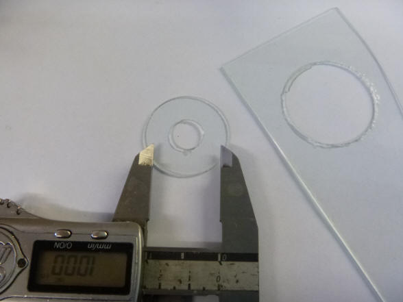
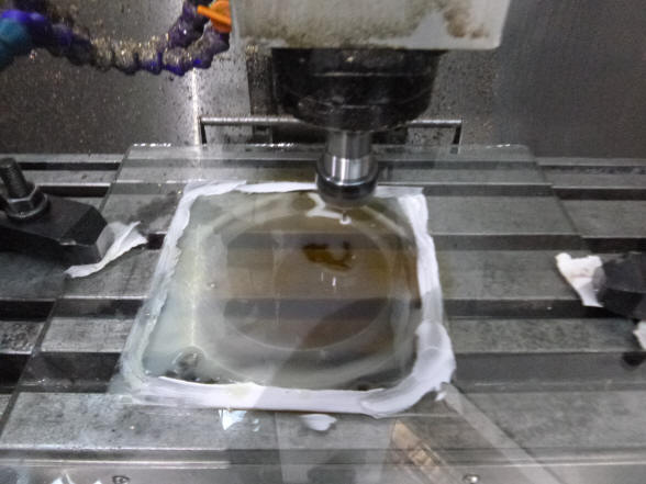
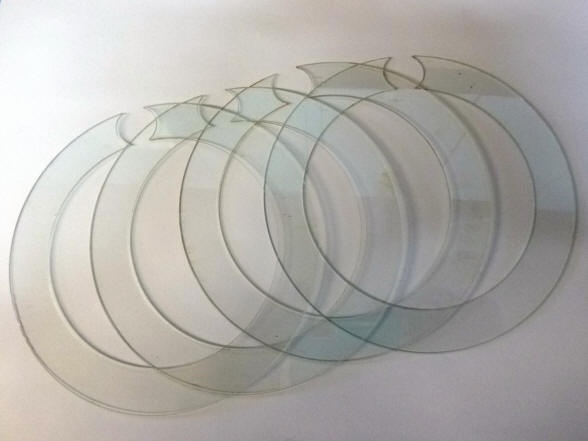
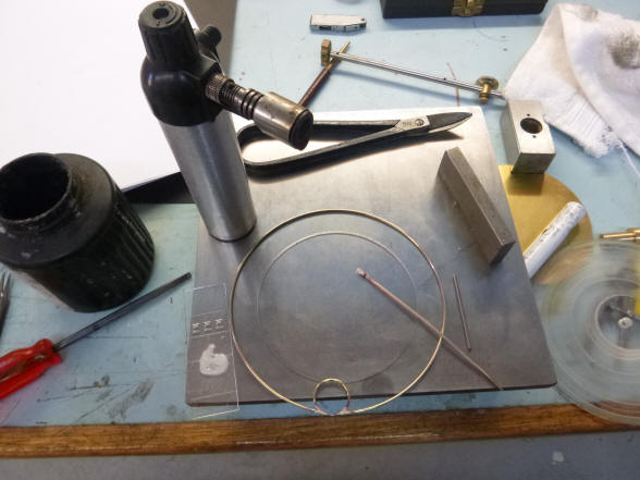
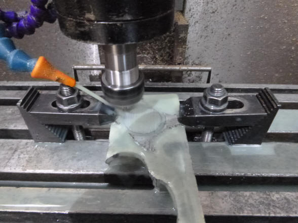
I have also had some success with the glass machining. As you can see
from the photos I cut a donut of glass 1 and 1/3 of an inch in diameter from
a sheet of 1.2 mm glass. This glass was clamped by its edges against a block
of aluminium and machined out on the CNC mill with a diamond burr. There as
a little roughness on the edges but it is almost acceptable like it is. In
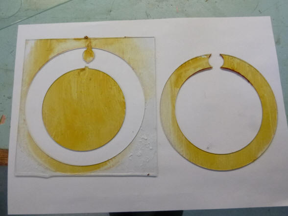
the next photo you can see I have glued the thin sheet of glass onto a thick
sheet of glass with shellac. I am going to see how much that will stop
splintering when we reach the other side. I am thinking that there will be
no stress in the glass as they have both the same thermal expansion and when
I warm it up in an oven afterwards I can just slide the thin sheet off and
dissolve the rest of the shellac with methylated spirits. I am rather
hopeful that this will work well.
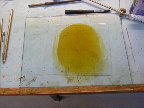
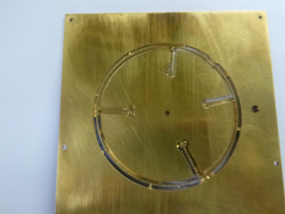
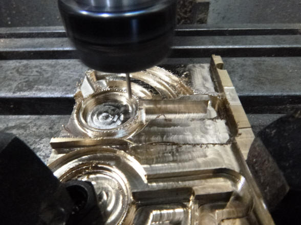
The CNC-controlled
diamond burr is used to cut the glass dial. The result with the glass being
shellacked onto another piece of glass backing is extremely good.
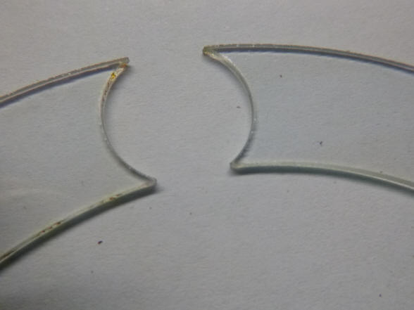
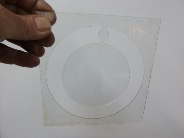
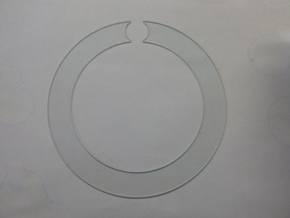
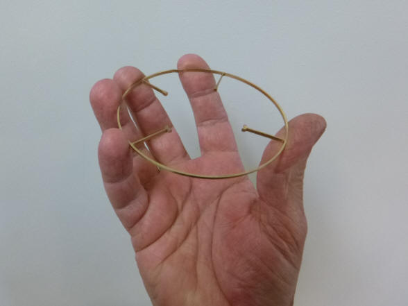
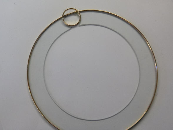
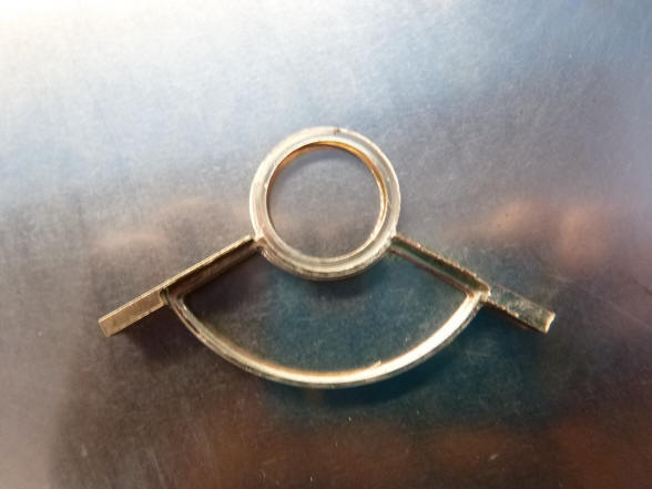
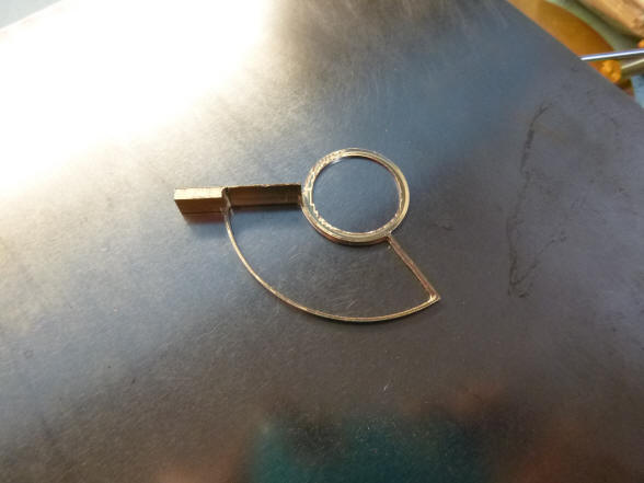
Look at the fine edges
and imagine how delicate this 1.2 mm thick open glass ring is. The second
photo shows the perfection of this process, the open ring was successfully
cut out from the background piece of glass without the center disk
breaking away from the extremely narrow neck, next the open ring. The
revolving moon will be located within the circular area.
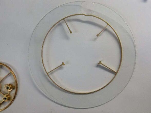
The inner bezel ring is
machined. Next it is positioned on the delicate glass dial to check for fit.
As one can imagine there is not a lot of room for error. The glass is held
to this bezel mechanically not
with adhesive. There is a small channel cut into the perimeter of the ring
for the glass to attach. This is made possible by the fact that it is a
C–ring and so has some flexibility to do this.
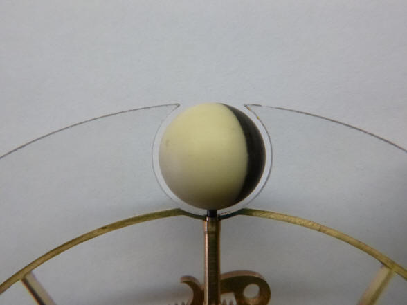
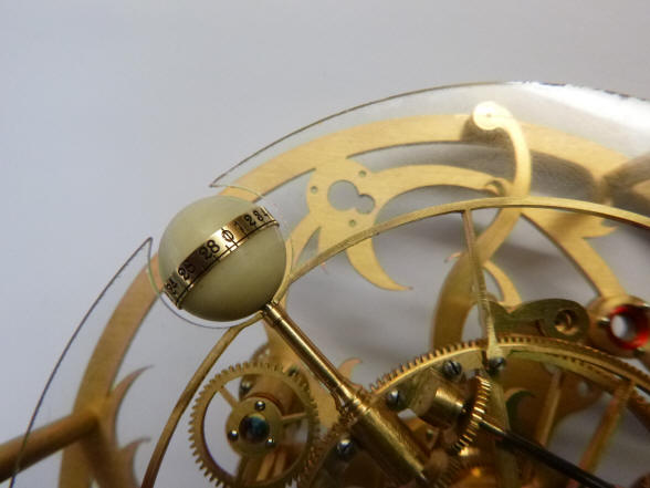
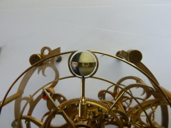
A delicate frame for the delicate glass. Next a close up of the moon sphere within the open area of the glass. The frame has yet to be finished, at this point it has a flat edge which will latter be rounded.
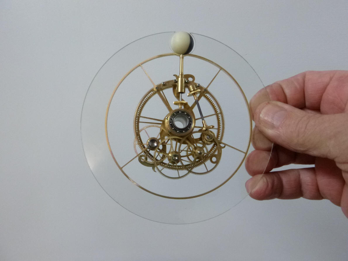
The glass is now
attached to the complete sun / moon indicator drive.
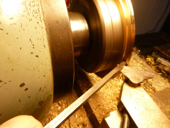
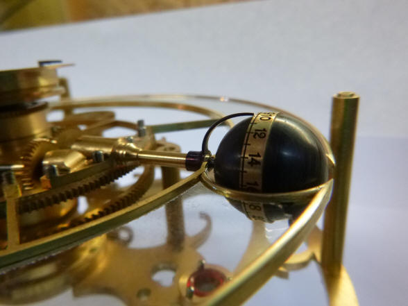
A brass blank is turned
for the age-of-the-moon indicator ring; next the completed ring around the
mockup plastic moon. The finished moon will be the same diameter as the ring
leaving it counter-sunk within the globe for a more elegant presentation.
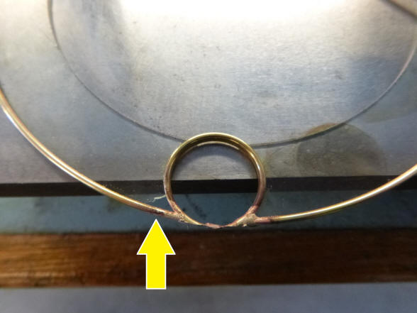
The ring for framing
the moon is prepared for soldering to the outer glass bezel.
Here the ring is
silver-soldered to the frame and one will notice the glass broke at the 7
o’clock position (yellow arrow). Good thing Buchanan made those extra glass
rings. Next the mockup moon is positioned within the ring. Notice the top of
the ring is open. This allows us to get the maximum moon diameter within the
ring as possible; with the ring’s base remaining. This is a must to retain
the glass ring’s structural integrity.
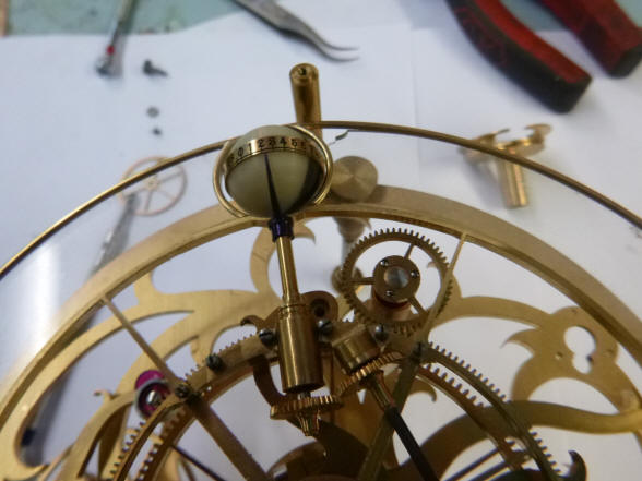
The age of moon hand is
fabricated.
Here the sun, moon
horizon shutters are being milled. A piece of light blue glass will be
inserted into the semi-circular space.
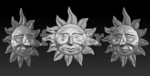
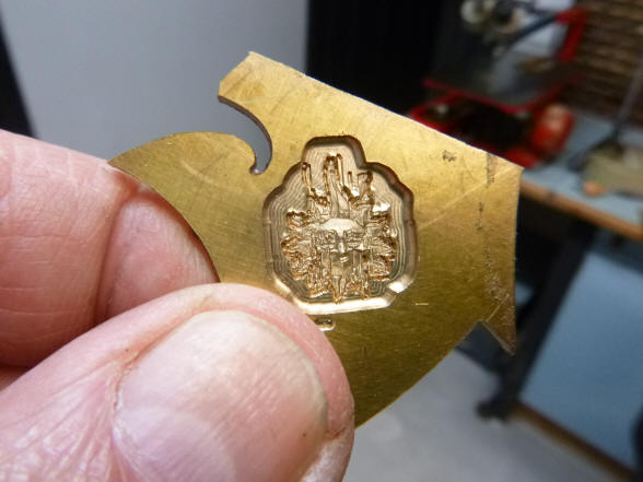
Buchanan went on line to look for a computer generated object that could be used on his CAD-CAM equipment to produce a nice representation of the sun for our project (see video below). In the second photo one can see that there was a bug in the program, the face looked like some villain out of a Marvel Comic - well things don't always work out the first time.
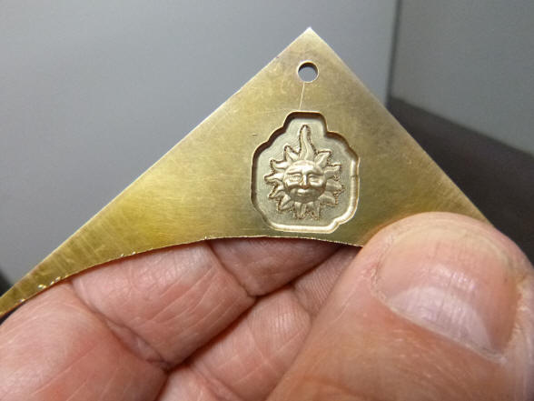
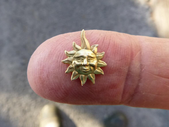
Finally the mill was behaving and a decent sun was
produced. The second photo shows the
finished product after further hand detailing and chasing; we have a
beautiful sun with a friendly, wizened face. The sun ray at 12 o’clock was
lengthened a bit since it will double as an indicator hand.
The sun will be mounted
to this pad, next the sun is seen at 11 o’clock.
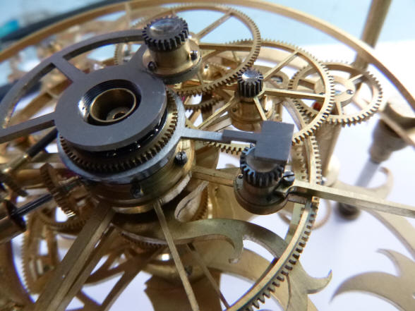
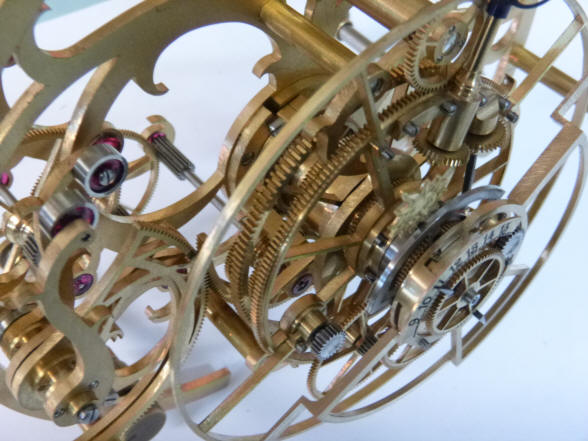
Next the dial is
attached to the brass backing. The second photo shows a steep three quarter
view from the top revealing the layering of wheels and dial indications.
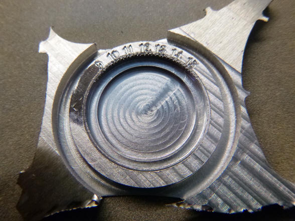
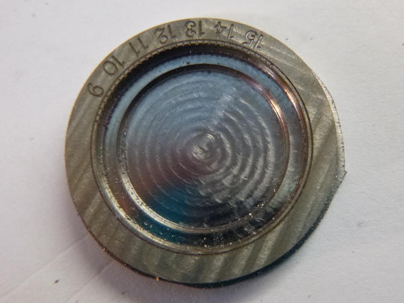
The steel dial for the
night hours is fabricated and numbers engraved. Cutting fluid flows over the
part. The day hours will be silvered brass.
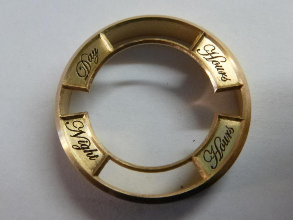
The bezel for the day and night hours is re-machined; the original had the night hours at the top with the day at the bottom, which is counter-intuitive.
A close up of the
cursive engraving. Next the dial labels and integral bezel are complete and
in the correct orientation.
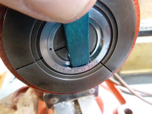
The engraved steel ring
blank, first photo, is ready for finishing, second photo. Here Buchanan uses
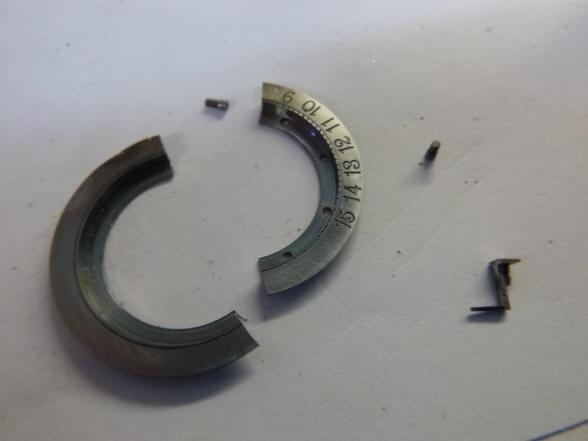
an abrasive stick to finish the surface on his lathe. Next the ring is split
to create the sector dial which is next mounted to one of a pair of horizon
shutters.
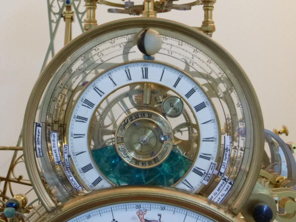
The two sector dials
are now mounted to the horizon shutter pair, silvered for the daytime and
black background for the night. One dial hand is blued for the daytime
indicator and silvered for the nighttime; each providing the correct
contrast to the dial background. Next the dial label bezel is installed with
the correct day / night orientation. |

![]()
![]()
![]()