|
Continue tellurion assembly, skeletonize frames - October 2015 This month we continue the fabrication of the tellurion complication.
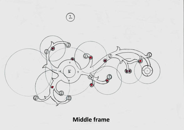
These are the final drawings for the bottom and middle frames of the tellurion. The curvilinear design continues the organic ivy vine theme used for all of our wheel work frames throughout this project. The red points depict jeweled pivots.
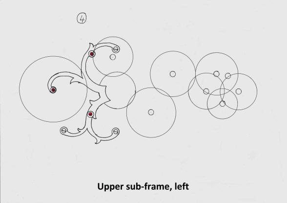
These two drawings show the two top sub frames. Actually these are proper frames in their own right, but are both smaller when compared to the larger middle frame they are mounted to. The entire wheel works are contained within three layers of frames. This arrangement is known as a double frame, as opposed to a conventional clock frame which has two plates holding a set of wheels and is known as a single frame construction.
Both the left and right sub frames are shown in position.
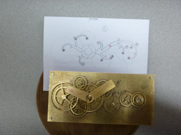
The final drawing for the bottom plate is posed next to the wheel works of the tellurion. Next the final design for the middle plate is transferred onto the brass blank.
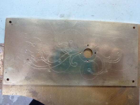
Next the etching for
the bottom plate is revealed. The last two photo shows both the top and
bottom main plates having their various pivot and plate pillar holes
drilled.
The bottom plate is now fretted out into the
beautiful frame that nearly disappears below the wheels. Next we see the
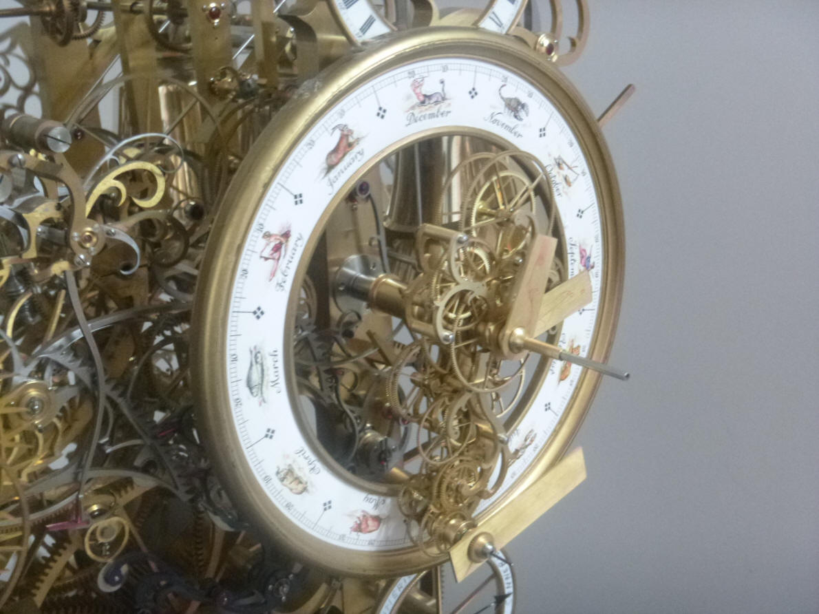
first initial fitting to the tellurion dial.
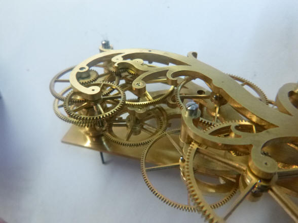
The two main frames are now complete. The density has increased considerably as seen in the second photo as compared to that shown above.
Here is a list of 'housekeeping chores' needed on the tellurion assembly; we also have a playful scene where the tellurion frame and wheels look to be smashed by the hammer above. Next is one of the top sub frames shown above its original drawing, note how it is a bit slimmer than the drawing. This as well as the rest of the frames in the tellurion will undergo further slimming and refinement.
Further frame refinements.
Here we see the actual assembly next to the build drawing. The six roller
bearings seen in that drawing are all neatly stacked within this diminutive
space.
Initial demonstration of the gearing to the Earth / Moon system. The armature upon which this as well as the inner planets of Mercury and Venus is also rotating. The very fast rotation of the small drill bit is standing in for the Earth's rotation and the arm around this is the orbit of the Moon. Of course the tellurion armature rotates once yearly.
Two views of the tellurion mounted to the clock.
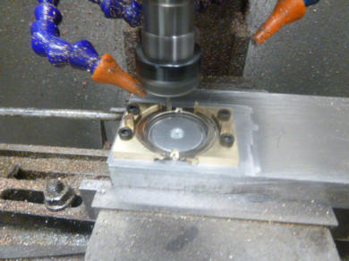
Buchanan now turns to the creation of the Earth globe. We had discussed the materials that we could use for this as well as the rest of the various planets and moons in both the tellurion and the yet to be designed, orrery. I had decided to use natural materials for these. The Earth will be made of walrus tusk which is the closest we can come to ivory, since that material is now impossible to obtain or import into the United States. We intend to add a black color to the surface lines for the latitude and longitude lines as well as the outlines of the continents in a method similar to scrimshaw. The Moon will also be made of this material. The balance of the planets and the moons of Jupiter and Saturn will be made from semiprecious stones chosen to match the colors of those bodies as closely as possible. At this juncture we are introducing a new methodology to the project through the use of computer-aided design and manufacture, CAD-CAM. When the project was first conceived, I expressly wanted to exclude this method. I have seen clocks made entirely by this method and they are immediately identifiable as such. They have a cold precision to the work that gives them away. This project exudes the warmth of a hand made clock by a master craftsman. The tiny variances and witness marks that can only come from hand fabrication and finishing is what makes this special. Having said this, the Earth globe is uniquely suited to CAD-CAM. We could have simply printed a globe onto a sphere or glued a sectional map to a sphere. But if we wanted to use natural material, then the only way to do this would be to engrave the features onto the globe. What the CAD-CAM allows us to do in this case is to create a sphere with the raised contours of the continents. Obviously at this scale the the continental contours are very exaggerated. If they were to scale the globe would be almost perfectly smooth. I think having an Earth globe with this feature would be unique and attractive. The first two photos above show the video display of the CAD-CAM machine. The Earth globe shows quite well in the first photo.
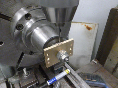
The first photo is a screen shot of the
numerical control setup for the machine. The next photo is the milling
machine setup.
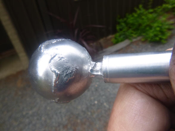
Here is a close up of the first test piece which is made of black plastic material. Next the globe begins to emerge.
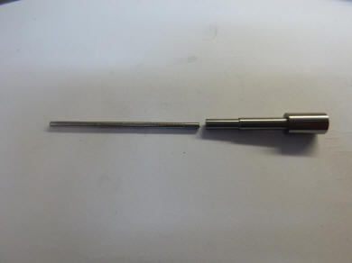
These photos show the next trial in metal, for this test Buchanan used aluminum, it is fairly soft and easy to machine. The first photo shows the sample in mid fabrication. This sample once removed from the machine could not be continued since it could no longer be aligned perfectly. A second sample is being machined in the next photo. The third photo shows a completed sphere with a close up of South America. Next some of the machine marks are smoothed out. The use of a finer cutting tool will eliminate most of the machine marks seen in the third photo making subsequent finishing easier. We will be making several samples before using the Walrus material since this is rather expensive. The globe is about 3.5 cm or just under 1.5 inch in diameter.
Here we see an initial trial machining of the Earth globe on the CAD-CAM mill.
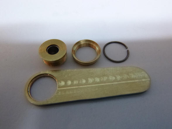
We now return to the remaining tasks needed to complete the tellurion. Here the armature clutch is made. As with all the other output components - the dial complications in the clock, there is a slip clutch to both protect the component from an accidental bump as well as allowing the dial component to be manually moved to allow setting in case the clock is stopped for a long period of time.
he main drive wheel hub is drilled and then tapped. Last photo shows a close up of the wheel with its set screw.
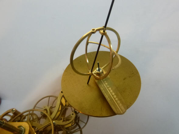
Here all of the major components of the tellurion driven by the wheel works between the triple plate assembly are demonstrated. Both the inner planets of Mercury and Venus, as well as the Earth's rotation and the Moon's orbit around the Earth is demonstrated. The entire assembly also rotates on the tellurion armature one per year.
The first photo shows the clutch for the Moon arm, Again each output component has a clutch so each can be independently adjusted. The clutch in this case is the 'C' shaped spring shown as the third component to the right in the first photo. This spring fits within the inner stepped area of the armature below. A rather clever and space efficient design. Next the wheel blanks are shown positioned on the armature.


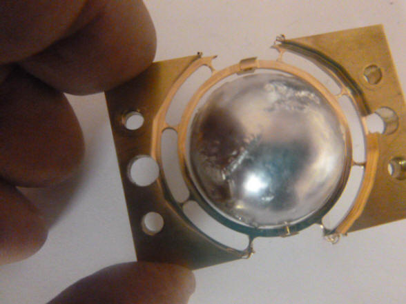
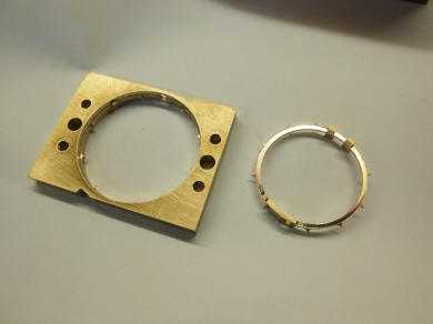
This set of photos shows how one of the rings that will support the Earth is
milled from the solid blank. There will be three of these delicate rings,
two that are stationary supporting the Earth globe and an inner one that
will rotate throughout the year in line with the Earth’s polar axis.
Here the preliminary fit is seen around the globe, it’s very close! Of
course now that the rings are being made we are stuck with the globe size.
But this should not be a problem if we are going the route of carving out
mammoth ivory material.
The filing button is secured within the jaws of the vise with the jaw
surfaces also used to support the ring. The small needle file is shown on
top. This file is used to remove all of the flash surrounding the perimeter
which one held it to the machining blank as well as the cutting tool marks.
|