Begin strike train fly fans - November 2010
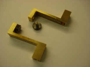
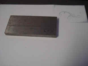
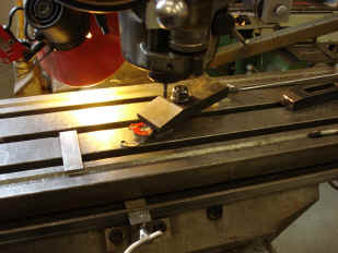
Now begins the fabrication of the two strike train fly fan assemblies. We based our strike fly design on Charles Fasoldt's fly fan in his famous tower clock of 1874 now in a private collection as depicted in Precision Pendulum Clocks, by Derek Roberts, pages 213-220. In his clock this mechanism acted as the device which allowed advancement of the motion works once per minute and acted as a buffer against adverse feedback from wind and weather upon the exterior tower clock dial hands. A form of remontoire for the movement as opposed to the escapement itself. The first parts to be made are the drive bevel wheels and their pinions. There will be a pair for each of the quarter and hour trains. Each pair has a bevel that originates at the power supply, that is the strike train and another that drives the fly fan assembly; which one will see as the fabrication progresses is quite complex. First a plastic mockup is made and placed in situ to ascertain how large a bevel can be accommodated at that location. The rough bevel blanks have very long teeth that will later be trimmed when the blank is cut to the final diameter. Due to differing space restrictions the two bevels at the fly fan level cannot be the same diameter. In order to achieve identical fly cycling, the pinions are adjusted to achieve the same rotational speeds between the two. Next the rough bevel drive brackets are cut from the brass stock. The fifth photo shows the cutting of the pinion teeth using a high speed fly cutter and continuous cooling cutting fluid. The rough parts are in the last photo.
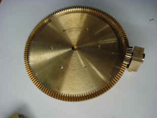
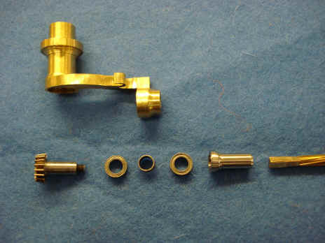
The rough parts are now finished and the bevel blanks are cut to their final diameters, second photo. The pinion is trial fitted with the bracket in the second and the third photos. The fourth photo shows B's characteristic fine wheel spoke work. Next the fly drive arbor and pinion are made. Notice the written drawings and calculations in the background. These are all done contemporaneously as the parts are being made. No pre-loaded CNC manufacturing facilities here!
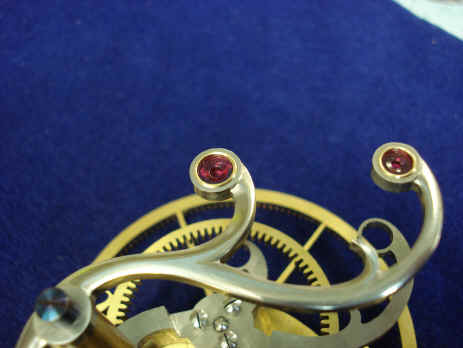
Next the bracket has the desired curvilinear design drawn onto it. Again this procedure introduces the 'human touch' of subtle variances between parts contributing to the overall warmth and beauty of a hand made device as opposed to many that have been made in the past two decades or so using computer aided design and modern fabrication techniques. The third photo shows a finished collet. The fourth shows an exploded view of the 'floating' drive pinion bracket on the fly fan. The last photo shows the completed assembly. This innovation is a critical component to this movement. The bracket is free to rotate and the twisted arbor is attached to a sleeve that allows it to be 'keyed' to the drive pinion but still slip just a bit in or out. The reason for this is the fact that we realize the entire frame assembly of this clock, due to its pillar design and our goal of making it as thin as practicable, is susceptible to error due to movement of the pillars under the stress of the weights. This has been discussed before and the clock stand should obviate this problem with its structural steel tube space frame assembly, (see September 2009). But we are designing into the clock a secondary 'fail safe' for all components that span between pillars. In this way if there is any small change in the pillars out of true vertical due to the base flexing under the mass of the weights, there will be no misalignment in the wheels or arbors
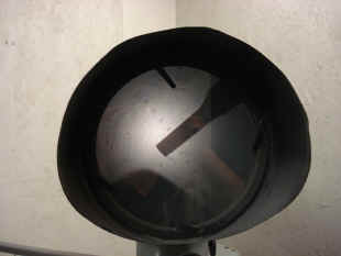
These photos demonstrate the tight conditions faced to bring the drive down to the fly fans below. B had to keep in mind over the past three years this accommodation as well as many others to avoid conflicts between parts.
The first component of the strike trains to be designed were the fly control governors. The various fly governors are a major visual component in this project. These are the parts that have the greatest visual attraction when activated and if designed properly also at rest. This special attention was demonstrated in the Wagner remontoire governors. These ultimately utilized a double fly assembly for each of the two governors. The first diagram shows this design much as originally envisioned by Fasoldt. Since I had already chosen a compound fly design for my remontoire I asked that this epicyclical fly be adapted for the strike train function. A four-blade fly, A, meshes with a wheel that has a long train stop piece, what we call ‘the whip’ and is attached to a wheel, B, meshing on the outside of a toothed, center wheel, C, fixed to the frame pillar, D. The whip and fly wheels are contained within a rotating cage (not shown) centered on the axis of the fixed wheel, E. The next two photos show the deficiencies we encountered. If the drive for the fly fan's detent 'whip' (the blue paper in the mockup) is driven in a conventional way with a pinion on the exterior perimeter of a drive wheel, the whip is too short to be visually appealing given the surrounding constraints of the winding arbors. Fasoldt's whip was twice the length, although he did not have any such obstacles to contend with. These photos show the dance that the whip will employ to avoid the two winding squares. If the sequence is properly timed the whip can be increased in length, but only marginally. See videos of the mockup demonstration below. This whip serves as a detent that will stop or release the fly at the appropriate time.
This diagram shows our revised version of Fasoldt's design. The main change is in the drive wheel for the whip pinion and its wheel which in turn drives the fly fan. We change this from a conventional toothed wheel to an internally toothed ring. This allows us to have a much longer whip. One, lesser reason for this is that the whip pivot point is brought inward a bit toward the center of cage since it is engaged on the inside as opposed to the outside of the drive wheel. However, the physics involved with the whip's pinion being driven by the internal tooth ring gear verses the conventional external toothed wheel causes the whip to take larger 'dips' relative to that achieved by a conventional arrangement. Buchanan drew the illustration purposefully to show how much longer the whip can be with the new design an increase of over 25% as shown by the length intersecting the winding square. In reality this situation could never occur since the hub of the whip would be geared at 180 degrees opposite to that shown.
The differences are described by these two animated illustrations. The first describes a conventional externally toothed wheel arrangement. The whip end scribes a petal shaped design, the red outline, known as an epicycloid. The second animation depicts the revised design. This red outline, known as a hypocycloid has much deeper valleys allowing us to have a longer whip and yet avoid collision with the two winding arbors. The whole point of this exercise is to create something that to the eye looks impossible. The whip length indicates that it should crash into the winding arbors, yet it does not. A secondary advantage to this change is that the whip now rotates in the opposite direction to that of the cage. This will appreciably reduce the locking forces on the assembly.
The first photo shows a drawing of an individual tooth profile from the ring gear. The inside diameter of the ring is under 1.5" (4 cm) and is too small to be cut with the tools that B used to create the much larger, 4" diameter internally toothed remontoire ring gears (see April 2008). The machine shown is an optical profile grinder. One component of the machine is a pantograph where the operator can trace the profile desired from the drawing shown in the first photo. Reduction achieved is 50:1. The viewer shows the operator what is happening as the grinding takes place and is at a 25:1 magnification, see also videos below. The third photo shows the tiny point fly cutter blank, the fourth the completed fly cutter profile in the machine's view screen. The last photo shows the copper anode blank next to the tiny fly cutter that will produce the tooth profiles.
The first photo shows the tooth profiles cut into the copper anode blank. Next the anode is being readied to be applied to the brass blank. Next one can see partial progress as the anode has cut about 1/8 its way into the brass blank. Next the blank is fully cut and the copper anode is inserted into the mating brass piece to illustrate the close tolerances that are achieved. The gap between the anode and the final part is only 0.002" or 0.05mm.
Now that the ring gear teeth are cut, the filigree support is fretted out.
The fly cage unlike the remontoire fly tourbillon cages, is made from steel rather than brass. I wanted to have a bit of color contrast on the front of the movement. The choice of material, however, precluded B from using the jeweler's saw as the blades did not go far before breaking. The first photo is a rendering of the front elevation of the cage. Next the steel block from which this delicate design must be wrought, then the initial rough blanks. These blanks were then attached to the mill bed, fourth photo, and the curvilinear outline was 'chain drilled' since the conventional saw method would not work. The next photo shows a partial cut. Next are shown 'filing buttons'. These are used as guides for B to be able to file a perfect circular perimeter around the various jewel holes in the steel fly cage.
The filing buttons are attached to several areas that need curvature profiling. Next a before and after view of the rough blank and the rough cage profile. The remaining photos show the filed cages being fitted to their drive arbors. Note in the last photo how the cage nests into the space inside the drive wheel ring.
The front cage frame surface is now elegantly chiseled, filed and shaped. These will reflect the light in such a way as to look like they are flying when powered. All of the flat steel stock, mostly located in the strike trains, will be similarly shaped. Astro_11-10_vid1 , Astro_11-10_vid2 , Astro_11-10_vid3 , Astro_11-10_vid4 , Astro_11-10_vid5
|


