Fabrication of pendulum balance assemblies - Complete balances, December 2008
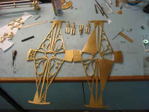
Photos show the balance plates continuing to be fretted out. The original hand drawing is glued to the blank surface and the design is then scribed onto the brass surface by tracing the outlines with a sharp knife. Then only the areas to be left are shown on the surface.
Next the actual cutting is done; again by hand on a small scroll saw. The fabricator can only do about an hour at a time before fatigue begins to sap his concentration. Remember, one slip and the entire part is ruined! The two plates were, nonetheless completed in less than one weeks time.
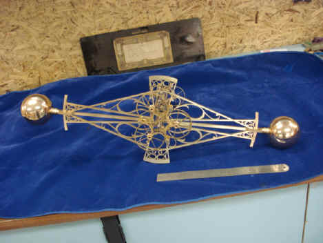
The completed balances are shown next to the original wooden mockup counterpart. Once again notice how the complexity and delicacy of the final design is a magnitude of improvement in esthetic appearance from the mockup.
The parts in metal lose the bulkiness that is apparent in the wood version. Overall length is just under two feet, 61 cm.
Notice in particular how much more delicate the antifriction wheel spokes and rims are as compared to the plastic painted discs on the mockup part. These parts are a major, if not the major, visual component of the mechanism. I am pleased with the outcome.
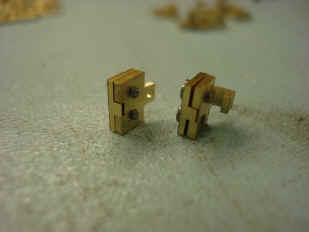
Finally the parts necessary to hold the balance springs as well as the bands that cross between the balances to keep them slaved together are made. I submitted quite a few photos of what is in the scheme of things a small and insignificant part to demonstrate the numerous steps necessary to create such parts. First the rough blanks are created like solders in a row. Various operations like slitting, second photo, and tapping, next photo are done with the parts attached to the mother blank. This makes fabrication not only easier, but more precise from part to part. It seems obvious, but a lot of thought has to go into what steps are taken in what order to avoid costly mistakes and remakes.
More slitting and other shaping operations. Last photo shows one piece of the final attachment assemblies.
Initial fitting of the band clamps. Next more tapping operations.
The final part is assembled. The size of this part is just over 3 cm or 1 1/4". The two knurl nuts are expertly executed. Check the sliding back plate in the second photo has beveled edges. Normally this would be left with straight edges on such a small part. There are a total of 8 attachment points requiring eight attachment assemblies. Each tiny assembly has eleven parts for a total of 88 parts.
First photo shows one of the four attachment assemblies located where the two balances nearly touch each other and will hold the crossover bands that keep the two balances slaved together. The second photo is of one of the assemblies that will secure the balance springs. This design allows one to attach and adjust the springs and cross bands with minimum effort. The larger knurl performs the adjustment function while the smaller locks it. Total number of parts for the balance assemblies, 424. Up to this point we have produced approximately 1750 parts.
The fabricator takes a well deserved look at his creation as it stands so far and as seen by the reflection of one of the balance spheres.
Astro_12-08_vid.mpg Astro_12-08_vid_2.mpg Astro_12-08_vid_3.mpg
|