|
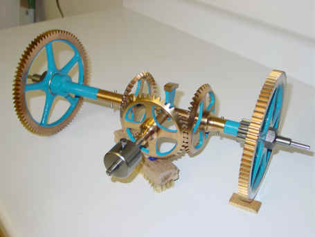
Edward Korfhage and Son, Buer, Germany, c. 1950's. Differential remontoire attributed to Augustin Lepaute, France. c. 1830 Gravity driven, train type. 60 second cycle. Remontoire dimensions 14"w x 7"h x 9"d. Part of the remontoire is shown below. Notice the fact that the wheels on both ends of the remontoire are identical. This is the usual application where the remontoire mechanically acts as an idler wheel - confering no mechanical ratios. In the first photo the output wheel is to the left, input to the right. This clock is electrically rewound so the fact that the weight drops fairly quickly makes little difference, hence no need for the mechanical advantage. At over 14" in width it is one of the larger remontoire.
Text of voice over narrative below: What you see is a greatly speeded up sequence of events that in real time would take 60 seconds. Notice first the rotating arm in the center of the picture just behind the cluster of the three bevel wheels. This arm is mounted to an arbor that meshes with the wheels connected to main weight of the movement. The cycle begins with the end of the arm at rest upon the face of a cam. This is the resting phase. A rod* is fixed to the cam at one end. In the middle is a bevel wheel which turns freely upon the rod and at the end is a small weight. The cam assembly rotates freely on an arbor that is perpendicular to the rod. Through the first 57 seconds of the cycle, the arm is at rest locking the drive train. During this time the fall of the small, cylindrical weight seen closest to the viewer is powering the entire escapement. As it drops, the center bevel wheel turns counterclockwise as it meshes against the stationary bevel wheel to its right which is connected to the locked main movement train. During this time the center wheel is also meshing with the bevel wheel on its left which is connected to the escape wheel. Since the right wheel is locked and the left wheel is free to move through the escapement, power is directed from the small weight through the center bevel wheel, to the left bevel wheel and to the escapement. The cam behind the center bevel wheel is also moving toward the viewer until the point that the end of the arm slips off its face. Now begins the recoil phase of the cycle and lasts about 2 to 3 seconds. At this point the main movement train unlocks and the right bevel wheel, powered by the main weight of the clock movement, begins to turn, meshing with the center bevel wheel. This happens at a faster rate than the bevel wheel to its left is turning. This difference causes the cam to rotate clockwise driven by the center wheel lifting the rod with its weight upward while the arm makes one revolution. At the end of that revolution, the cam face has moved back into its starting position blocking the arm and locking the main movement wheel train again. All the while power is uninterrupted to the bevel wheel on the left driving the escapement. The center wheel keeping a constant power supply to it throughout the remontoire cycle. The sequence should be seen as the small weight giving a constant source of power to the escapement at all times. The small weight’s kinetic energy is recharged periodically from the larger clock movement’s main weight before it exhausts its energy by reaching the end of its limited travel. The left bevel wheel to the escapement is always being driven, the right bevel wheel is always a driver, while the center wheel always drives and is periodically driven. This is the principal of a differential gear system. The differential is the general mechanical concept employed in all gravity driven train remontoire. The action you see especially in the rotation of the escape wheel is necessarily distorted. The time the remontoire is at rest is far greater than its recoil phase. So to make the animation fit into a reasonable sized file the resting phase was greatly speeded up while the recoil phase was slowed down a bit. * The term rod is used for a fixed object that would otherwise be termed an arbor if that object were allowed to rotate. |