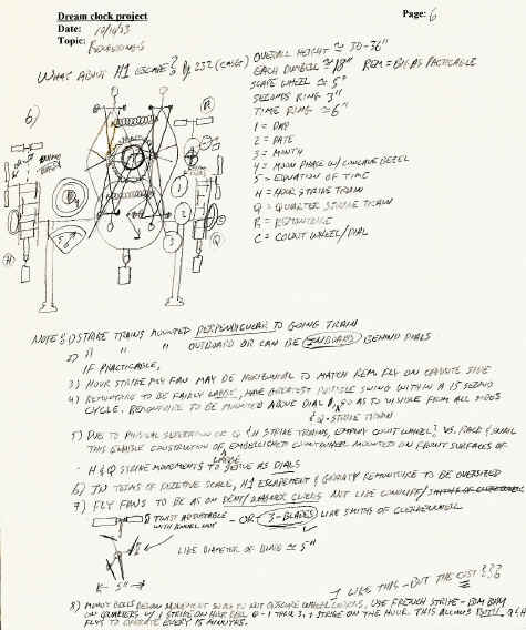
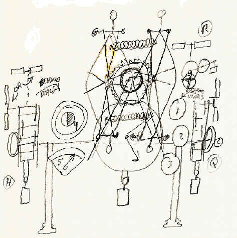
Below are samples of initial design concept drawings in chronological order (beginning in October of 2003). At first I was working along the lines of a tower clock as seen on the first page. At this point the escape wheel is at the rear of the movement. The second page shows the embryonic concepts for the clock. Here begins the H1 escapement with the center-positioned escape wheel. Several of the subsystems are listed: calendar, equation of time, a moon phase globe, remontoire, quarter strike trains. Multiple bladed flies are explored (later became compounded as well).
Initially, the strike trains are positioned at right angles on either side of the going train to encourage viewing at all angles (later abandoned). Notice in the first drawing the two flies at either end for the strike trains. This placement of flies at both ends of the clock remained through to the final design (although they changed from strike flies to dual remontoire flies) as well as the centrally placed escape wheel and H1 type balances. The second drawing shows experimentation with dial placements.
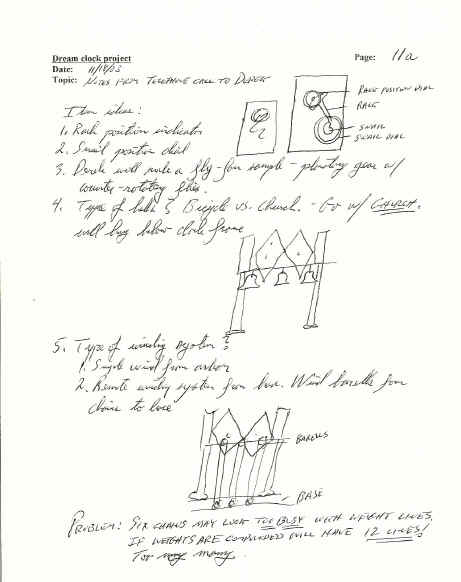
Now the remontoire is moved to the top-center of the movement. At this point I began to experiment with a CAD program, but the learning curve was too steep for a one time project and I went back to free-hand drawings. However, one can begin to see the initial dial layout and placement. This was completely altered later.
Here I try a side elevation with the CAD program. It shows the strike trains using a count wheel system. Initially I chose this to maximize the use of wheels with indicators. In the next drawing I switch from count wheel to rack striking for the strike trains, next the placement for the bells is explored.
|