Escapement antifriction wheel assembly and escapement wheels, September 2008
Below photos show the bevel drive wheels from the going train (upper set) as well as the their sister wheels to drive the escapement wheel assembly (lower set). Note in the last photo the true angles milled into the pinion and wheel teeth for a smooth bevel mesh. Unlike most conventional bevel wheel setups that consist of a 90o shift, this has a custom angle of about 120o.
First shot is the bridge with jeweled pivots that will hold the positioning antifriction wheel. Second shows this part with mating wheel mounted to its support. Lastly all of the antifriction wheels mounted to their rough plate mounts.
The antifriction wheel assembly now with the two escapement wheels in the solid. Second shot a close-up of the two positioning antifriction wheels. The two escapement wheels rotate independently and in opposite directions to each other. Each escapement wheel's arbor rotates upon an independent set of antifriction wheels (4). Anytime one uses this type of system there must be some method of controlling end shake. In this application, the sideways movement of the arbors would be severe since each has a bevel wheel. Anytime a bevel set is employed there is considerable side thrust produced; the two bevel wheels try to push away from each other. The two horizontal antifriction wheels keep the two escapement arbors from being pushed sideways by the bevel wheel sets.
Further shots of the escapement antifriction wheel system.
These shots now show the rough plates now cut out into the cock pairs that each hold two antifriction wheels.
Some perspective shots.
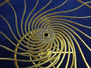
Now begins fabrication of the two grasshopper escape wheels. The first four show the teeth being cut. Second photo shows a template that was made from the original working mockup design made in Plexiglas back in April of 2006. Unfortunately no photos were made of the spoking out process of the wheels themselves. But it was done on a small jeweler's jig saw under a stereoscopic magnifier.
The final result is striking.
Photos of the completed escapement assembly on its rough platform.
The second photo shows the escapement assembly on its rough platform; inserted into its place within the movement. After everything is complete and tested, the entire mechanism will be disassembled and the final forms for the pinions will be machined. Some will have their widths trimmed and the sides will be dished. The collar on the inside of the bevels as well as their overall width will be trimmed.
Notice how the two drive arbors are are parallel. This was difficult to achieve and required much planning to match the width of the bevels on the escapement assembly to those on the going train remontoire. Again, the mockup was invaluable to this, as those were also made parallel. In this way the fabricator knew approximately how far apart the going train drive bevels had to be, and thus the entire remontoire assembly. Too much in one direction or the other, and it would have been impossible to achieve this elegant symmetry. These arbors rotate fairly quickly and so will later be made into the twisted barber pole style with the twist travelling from the remontoire toward the escapement. The barber pole arbor that is currently in place to drive the right hand fan will be replaced with a thinner version.
Astro_09-08_vid.mpg Astro_09-08_vid_2.mpg Astro_09-08_vid_3.mpg Astro_09-08_vid_4.mpg
|