Sargent & Greenleaf, Rochester, New York - 2 movements, Model #2 version 1, 2 and 4.
![]()
![]()
![]()
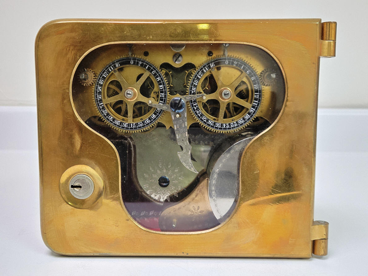
In 1874 S&G introduced their Model #2 time lock. This was their first time lock-only model that operated directly on the bolt work of the safe. Their Model #1, which was introduced at the same time, operated by disabling the safe's combination lock and was a part of and located within the time lock case. The example below is the one of three known complete examples of the earliest Sargent and Greenleaf Model #2, this example being the second lowest serial number ². At the time it was marketed at a hefty retail price of $400 which translates into nearly $9000 today. The earliest known version of Model #3, and the Model #4 were smaller and designed to fit within tighter door configurations but were still priced the same $400 retail price. This remained the most expensive time lock until the introduction of Yale's Model #1, in 1876 with the Sunday dial attachment coming in at $450. Not surprisingly Yale's standard model, introduced in 1875 was priced at $400. The only other time locks to exceed these prices were the Consolidated Time Lock Company's Dalton Dual Guard introduced in 1884 at $500 and the combination of the Dual Guard and Permutation locks in one unit known as Triple Guard for $600 in 1888; the most expensive time lock in real dollars ever produced. Keep in mind that these prices often exceeded the value of the entire safe upon which these devices were attached!
 A
A


 A
A
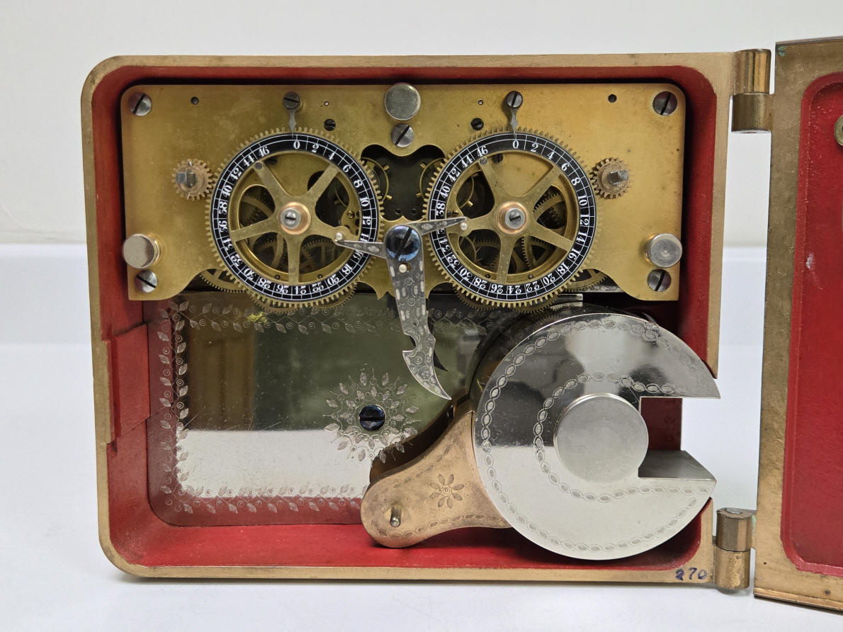
These photos show the auxiliary bolt needed to make the roller bolt configuration work . The rollerbolt was used in Sargent & Greenleaf's successful combination locks as a way to prevent a safe cracker from using the exterior bolt work release mechanism to run the bolt work against the the combination lock to decipher the correct combination. This was a bit difficult to transfer to the working of their time lock. This auxiliary bolt was attached to the moving part of the bolt work. Closing the safe meant opening the auxiliary bolt (first photo), winding the time lock movements, hooking the rollerbolt up (locked), and closing the and locking the door. As the boltwork closed , the outer sleeve of the of the auxiliary bolt with it while the flat end of the inner piece would abut an inner part of the door. The sleeve would slide until until the auxiliary bolt snapped shut, (second photo), time locking the door. There are only two auxiliary bolts known.
![S&G[1].JPG (1147880 bytes)](SG1.JPG)
![S&G[1] (1).JPG (1142687 bytes)](SG1_1.JPG) B
B
The prominent feature of this time lock design is the rollerbolt on the lower right of the lock. When it is rotated clockwise causing the pin mounted to the tail of the roller bolt to rise, the pin will engage the notch on the drop lever which is mounted to the movement plate and controlled by the rotating dials of the time lock movements. The rollerbolt was first introduced in the James Sargent Magnetic Rollerbolt combination lock in 1866. This innovation moved the dogging action of the lock from the tumblers themselves to the fixed bolt axle, further isolating the tumblers from any attempt to read them through the boltwork. In the time lock its function is restricted to dogging the bolt work. Another interesting feature is the fact that the door is a flush mount, note the lower right hand corner of the photo above. Shortly after the introduction of their production, S&G switched to their 'clamshell' style of door having an overhang around the door edge (excepting the hinge side). This style was used throughout their numbered series of locks, model #2, #3, #4. By the time their #6 was introduced about 1910 S&G began using a flush door design the same as Yale had been using through the life of their manufacture. There was an example with a countersunk door design used in their model #4 Corliss and was similar in design to what Hall and their successor Consolidated used in their case designs. S&G's early locks models featured the "Security Red" paint color on the interior of the case and door.
![S&G[1] (2).JPG (961158 bytes)](SG1_2.JPG)
![S&G[1] (3).JPG (1057505 bytes)](SG1_3.JPG) B
B
When this lock was used in a safe, the owner used a black crayon to block the 48 hour mark so as to avoid the lock being wound past 46 hours, its actual maximum duration. I left the crayon marking on the left dial as an historic artifact.
![S&G [2].JPG (2099799 bytes)](SG_2.JPG)
![S&G [2] (1).JPG (2064671 bytes)](SG_2_1.JPG) C
C

 D
D
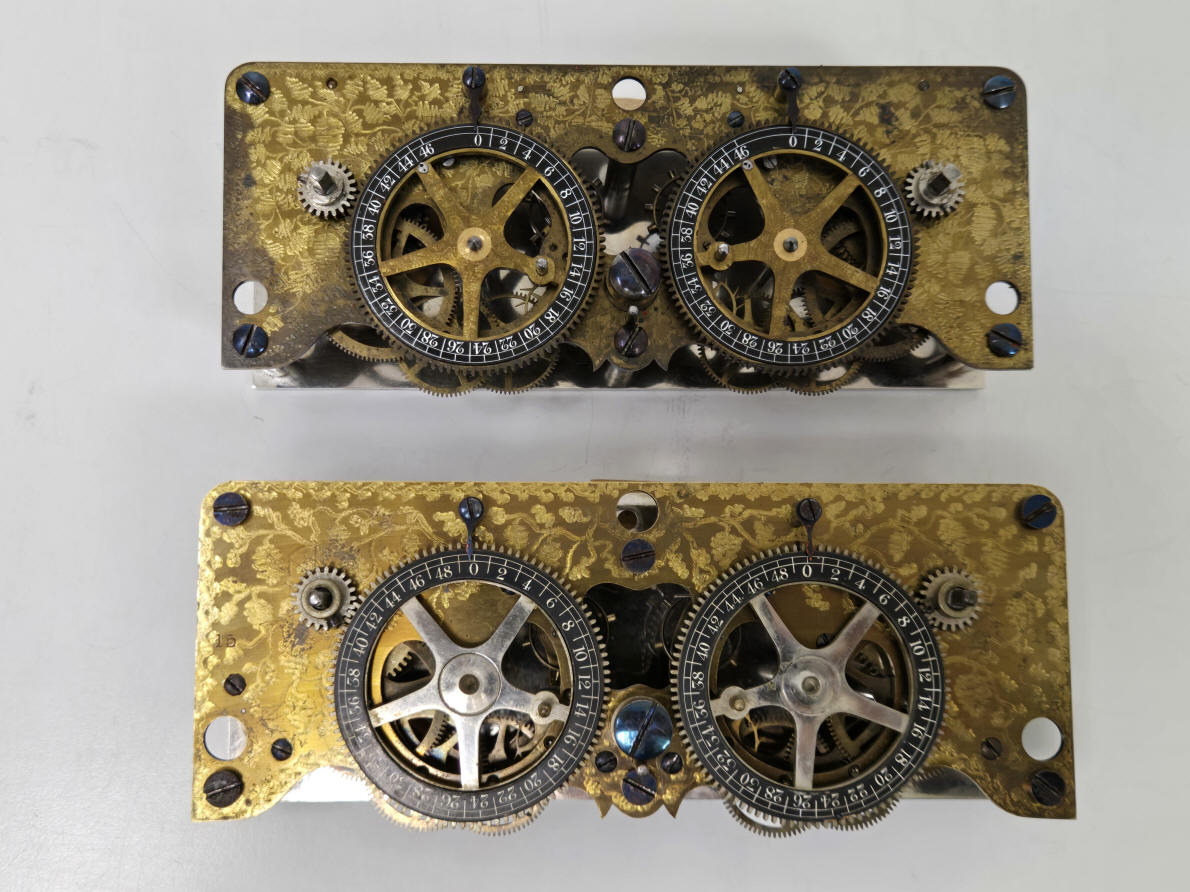
These two photos illustrate the differences between the earliest S&G movements. The upper movement is an S&G Model 2 v.2. s/n 129. It is identical in all aspects to the Model 2 v.1 except in the dial duration. By this time it was correctly reflecting the actual spring duration of 46 hours. The v.1 showed 48 hours. The lower movement is s/n 15. S&G had intended to subcontract the their movements to Seth Thomas and this is one of those. S&G found these to be unsatisfactory and only twenty were ordered. Afterward S&G switched to making their movements in-house, something unique to S&G; all other time lock makers did sub-contract their movements and in many instances the entire time lock. From the front the obvious differences between the Seth Thomas and the S&G in-house movements were the spoke-finish of the dials plain finish vs. vine and ivy design as seen on the movements plate, grub screws to secure the winding cogs vs. being pinned, screws securing the movements plate being flat cheese head vs. domed design.
 E
E
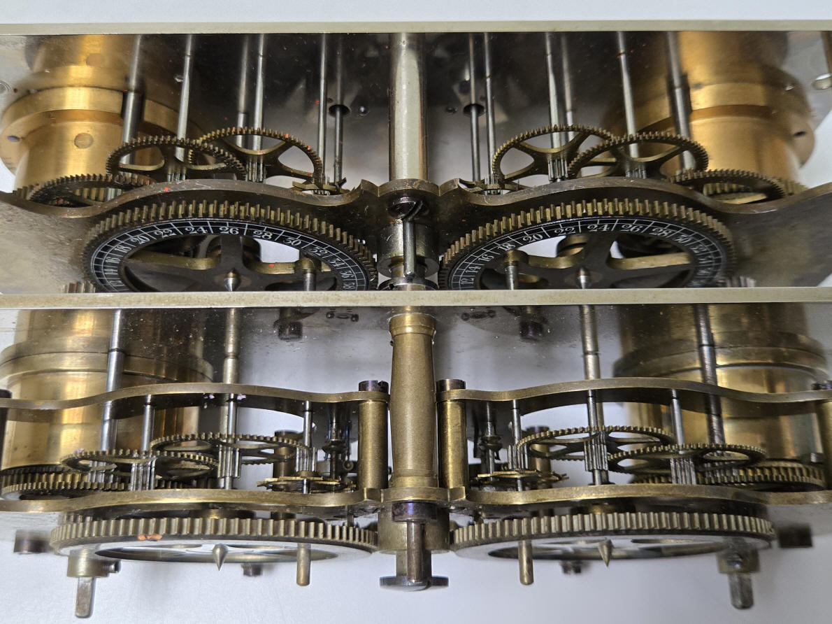
An inside view shows more significant differences. Again the Seth Thomas is the lower movement. Here one sees a triple-plate design where all arbors except those supporting the dials, are between the front full plate and middle bridge plate. The upper movement representing the typical S&G in-house design is a conventional two plate configuration with all arbors spanning between the two. The triple plate design allowed for the wheels to be of a conventional configuration and Seth Thomas would have naturally gravitated toward this. The early Seth Thomas movements only had a pair of jewels for the balance wheel. The first movements from S&G included jeweled escapement fork pallets, and the v.2 added jewelling to the escape wheel.
The Seth Thomas movement is prone to the balance wheels unexpectedly locking, especially upon initial start up. This is due to the impulse pin coming out of synchrony with the fork and is the result of the overall quality of the movement not being up to that needed for a time lock. In a pocket watch a slight jostling of the movement can return the system to operation, but this is not possible with the mechanism secured to a safe or vault door. The maintaining power pawl springs are poorly designed and prone to slipping out of alignment.
A. Model #2 version 1, (later no. 6206), 1874. What distinguishes version 1 from all other Model #2 versions are the dials which indicate hours numbered one through forty eight. However it only had mainsprings that would power it through forty six hours of power and this model was sold with instructions warning the user not to wind the the movements past 46 hours.(1) Obviously this was not a very good arrangement which probably did not reflect well on the product and so was very soon changed to the dials being numbered through forty six hours (why longer duration springs being fitted is not known). It is interesting to note that the two examples of S&G's Model #1 both have the forty six hour dials. It is not unreasonable to believe that this example could be earlier in manufacture than the two known Model #1's or that they were later retrofitted with the forty six hour dials.
There is a small pin fitted below the dial that engages with a lever that is attached to the escapement fork as the dial approaches zero. When engaged, the movement stops and corresponds to zero on the dial. There is always a danger in having anything interfering with the delicate escapement. On the other hand, one does not want the pin that is mounted to the front of the dial which engages with the rollerbolt release lever to act as the stop since there is still a great amount of torque even at the zero point. This is necessary as one must ensure that there is sufficient power at the zero point to activate the release lever. Sometime between the introduction of the the cello bolt about 1877 replacing the roller bolt this was redesigned with a stout pin mounted underneath the dial which engaged with another pin mounted to the movement plate providing a positive stop to the dial and taking all of the torque. This obviated any contact with the the escapement mechanism as well as any pressure on the dial pin related to the lever release for the cello bolt (formerly the roller bolt). There are only three known, complete examples of Sargent's model #2, v.1.
Another feature of the very earliest locks made by S&G is the deep, rich gold filled damascene jewelling on the case and roller bolt. The earliest locks also had elaborate vine-like engraving on the movement plates as well as the dial spokes. Another change that was made very soon after the lock's introduction was to alter the way the dials were attached. Changing them from being permanently mounted to their arbors (photo three) to having them secured with a screw making servicing much easier (see example D). 6.5"h x 7.75"h x 2.75"d. Case #49, movement #38. file 362
B. Model #2 version 1, (later no. 6206), 1874. This example is similar to 'A' above. Notice in the second and last photos the right hand dial has the last numeral, 48, partially blacked out with crayon reflecting this situation. Originally both were, but I removed the the covering on the right dial to better reveal the last number. The last photo also shows the stop screw as well as two open, threaded holes. Near this screw on the dial is a corresponding pin attached to the end of the wheel spoke. When the pin comes into contact with the screw the movement stops and is provided to avoid the dial from turning too far and jamming up against the snubber bar (the release lever for the bolt). Apparently there were a few trials and errors in the positioning of this part on the very early units. This was an attempt to change the design from the dial pin below the dial from directly engaging the escapement. I've never seen additional stop screw holes on any other S&G lock. 6.5"h x 7.75"h x 2.75"d. Case #40, movement #43. file 91
C. Model #2 version 2, 1874. This lock is identical in all respects to the version 1 except that Sargent lowered the numbering on their dials to reflect the fact that it could only be relied upon to operate for 46 verses the 48 hours on the original version 1. There are two known versions of this model with the glass door. John Erroll's book shows another version 2 with the solid door used in coin safes making only three known survivors of the version 2 movement. 6.5"h x 7.75"h x 2.75"d. Case #129, movement #129. file 158
D. Model #2 version 4, 1876. This lock is similar to the original time lock invented by James Sargent and first put on a vault door in 1874 (see above). Major changes were in the way the dials were secured. They now were held by a screw rather than being permanently secured to the dial arbor, making their removal far easier, also the case area where the decorative plate was located behind the roller bolt was strengthened with a raised lattice structure. Jewelling was also added to the escapement pallets. A minor change is the use of slot-head bolts to secure the movement to the case. The three prior examples used similar bolts but those were also threaded on the shaft near the heads to allow for a decorative metal 'button' to screw on to cover the top of the bolt; the decorative ivy engraving on both the top movement plate and dial spokes was eliminated and the roller bolt decoration was somewhat simplified. Only the first four years of the production run, 1874-1877, of this lock had the black enamel dials. The Model 2 had many changes over the years of it's production from 1874 through 1927. John Erroll's book divides these changes into 15 styles through this period. Although this version made for just over one year it was the first time lock to get a longer production run, thought to be between 150 to 200. One of seven known completely intact examples. Formerly from the Harry Miller collection. Another example is in the John M. Mossman collection in the Museum of The General Society of Mechanics and Tradesmen, New York, NY. The rest in private hands. Case #531, movement #535. file 101
Compare this example to the other S&G model #2 locks on the next page. Also compare to a similar rare vintage model #3 with the same dial and case features.
E. Model #2 version 1, pre in-house S&G movement. In 1874 when S&G first began production of their Model 1 and Model 2 time locks the company sub-contracted the movement's manufacture to the Seth Thomas Clock Co. Only twenty were delivered before S&G cancelled the order due to unsatisfactory performance. It was prone to the balance wheels unexpectedly locking, especially upon initial start up. This is due to the impulse pin coming out of synchrony with the fork and is the result of the overall quality of the movement not being up to the standard needed for a time lock. In a pocket watch a slight jostling of the movement can return the system to operation, but this is not possible with the mechanism secured to a safe or vault door. Other issues include the maintaining power pawl springs are poorly designed and prone to slipping out of alignment. Below is a time lock purported to be s/n 8. If unaltered, it would have a Seth Thomas movement. file 386


(2) It has recently come to this author's attention that an earlier version, serial number eight exists. Although I have not personally seen this, I believe it to be genuine. From the photos I have been provided it appears to be similar in construction to later models. It appears that the winding arbor gear is attached via a grub screw vs., later being pinned, the dial spokes appear not to be decorated in the same manner as the front movement plate but left plain, although this could be the result of oxidation. Overall operational condition is unknown. The movement, if the same or within a few digits of the case number would place it before serial number 20 meaning it was made by Seth Thomas, see example movement above.


This shows a S&G model #2 version 3 with a Hall combination lock size #3 installed in a Diebold safe. The auxiliary bolt is seen to the right of the lock that was needed in the first rollerbolt design. The cello bolt design allowed S%G to do away with this ancillary part.²

This is an illustration from a Detroit Safe Co. catalog, c. 1875. The drawing clearly shows a model of #2 time lock still using a rollerbolt with the auxiliary bolt. Version [5] was the last to use this before the introduction of the "cello" style drop bolt in version [6] in 1877.
![]()
![]()
![]()
(1)American Genius Nineteenth Century Bank Locks and Time Locks, David Erroll & John Erroll, pg. 150
(2) Photo curtesey David Deckel, 2022.