|
Maker, Warren Telechron, Inc., Ashland, Massachusetts, USA. Model Type C, 1926, serial no. 7. Page 3. Restoration. Fabrication of missing parts. As received the clock was in some disrepair. In addition to the usual cleaning and maintenance that would be expected, there were missing parts as well as work needed on the wood case. I will describe here the work needed for the movement itself. As far as I know only one other example of the Type C; currently inoperable is known and it too is missing the following items listed below, as well as a few others.
Author's note: Four years after the restoration was complete, there was a sale of Henry Warren's personal secretary's effects having many personal and corporate papers and other ephemera in connection with the Telechron company, there was also a box small containing an original Type C tilt table and set of mercury switch tubes (see below). Given the small production run of the Type C and with only two known to survive, what were the chances of that? The first thing I needed to do was to try to get as much information on this clock as I could in order to reproduces as best I could the missing parts. Fortunately there were a few very good pictures of this clock and movement in the NAWCC Bulletin, August 1991. These photos were attributed to file photos from the Hall of History Foundation, Schenectady, NY. I tried to contact this entity for further information but this proved fruitless. So I went with the photos I had. The first item tackled was the most complex, the tilt table. Without this part the clock was hopelessly useless. It also has quite a visual appeal as it moves and has the glass mercury vials mounted to it. All of the parts excepting the simple wire harness were made by the firm of Buchanan, the same firm involved with my commission astronomical clock.
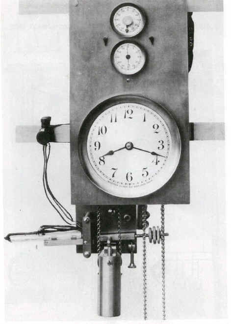
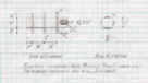
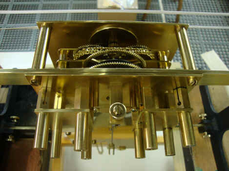
Above is the best photo available from the Bulletin article, next the movement as found, the drive weight is present but not shown. Fortunately the bridge for the table pivot was there, so the overall width of the table arbor, pivot length and diameter as well as the width of the table itself was readily calculated.
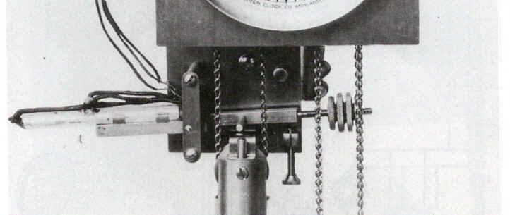
A close-up the section we are interested in fabricating including the tilt table, mercury vial mounts and counter (poising) weights.
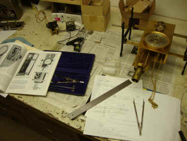
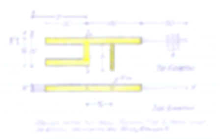
Using the photos and what was extant on the movement a drawing was produced (drawings are pixilated for proprietary reasons).
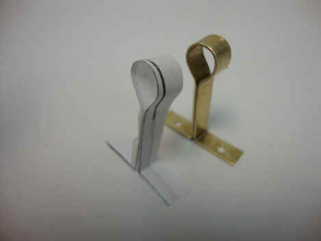
Next a paper mockup was made to be sure it would fit properly within the confines of the movement and have the same proportions as the original in the NAWCC Bulletin photos.
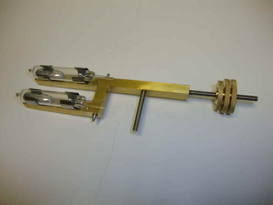
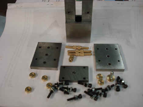
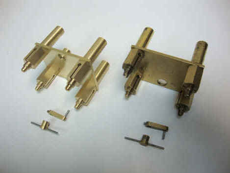
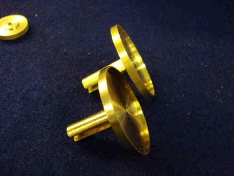
The completed tilt table assembly along with the mercury switches. We were able reproduce the table and the trim weight with good precision from the archive photos. What I was not able to do was to get the exact shape of mercury switches. These are shorter than those shown in the file photo taken from 1920.
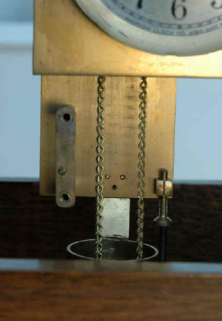
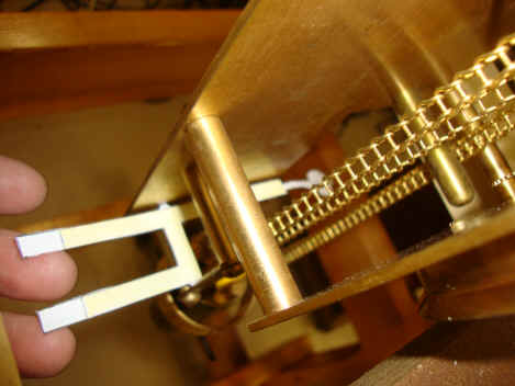
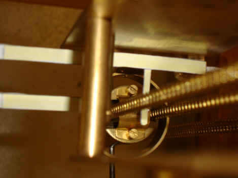
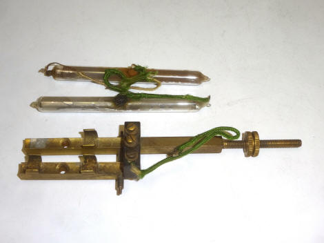
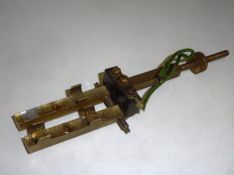
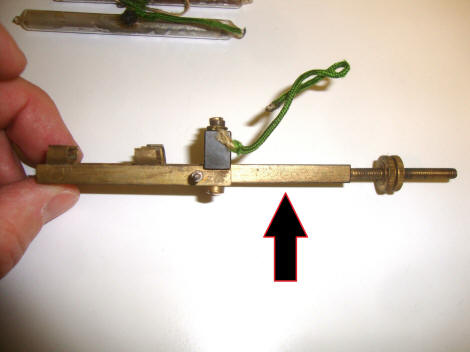
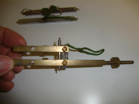
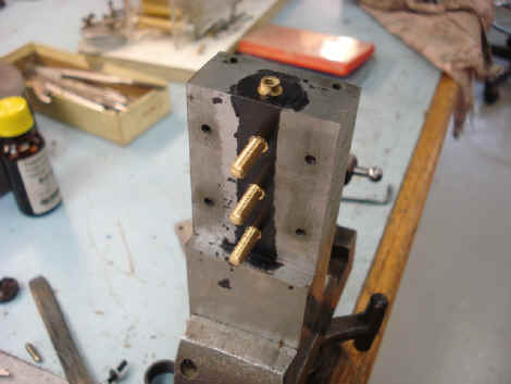
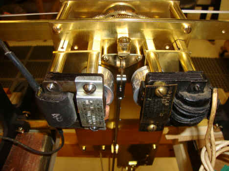
These four photos show the original tilt table as found four years after the replica table and clock restoration were complete. What I could not see from the extant photos was the Bakelite connecting post which was also used to secure both mercury tube holders. With hindsight, I should have guessed this. It would be possible to mount a similar mounting post on the replacement table at this point to replicate the electrical mount. An curious point is the lack of the tilt-touch post that should be mounted on the surface facing the viewer where indicated by the arrow, third photo. There are no witness marks to show such a post was ever present. That post is an essential component for the table to function and is clearly shown in the historical file photos. Other than this the table is fully functional with the clock. Perhaps there was a design change after this table made; before that there may have been an extension mounted to the weight designed to touch the table as configured. The original mercury switch tubes are too damaged and fragile to use and replacement tubes that would fit the configuration of the table could not be located. Since the tilt-table is necessary for the clock to function, I decided to keep the replica table and safely store the original with the clock for a possible future solution.
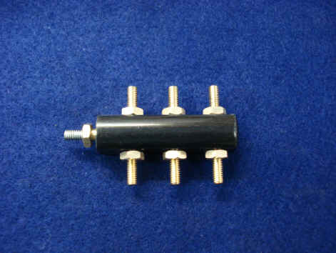
Next a drawing is produced for the connector block based on the file photos determined in the same manner as was the tilt table. The block is made of Bakelite in the same manner as would have been done in the 1930's. Die casting is exactly the way the original would have been created at that time. For the remaining parts that needed to be fabricated we had a set of originals in the existing movement.
The first copy from original parts is from the one existing motor mount and drive gear. The clock needs only one motor to operate properly; with the second able to be put immediately into service should the first fail. This motor redundancy was also incorporated in the Type A. The original mount is on the right. A second motor was also installed.
The next copy is the reserve weight tray attached to the movement frame. Reserve weights are kept here for later use on the pendulum weight tray. I had a reserve weight tray on my Type A which was a perfect fit, so this was used to produce a duplicate for this clock. The next photo is a wire harness. There were two empty holes right where the wires would normally pass so I made a paper model to be sure of tolerances.
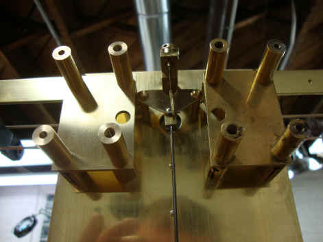
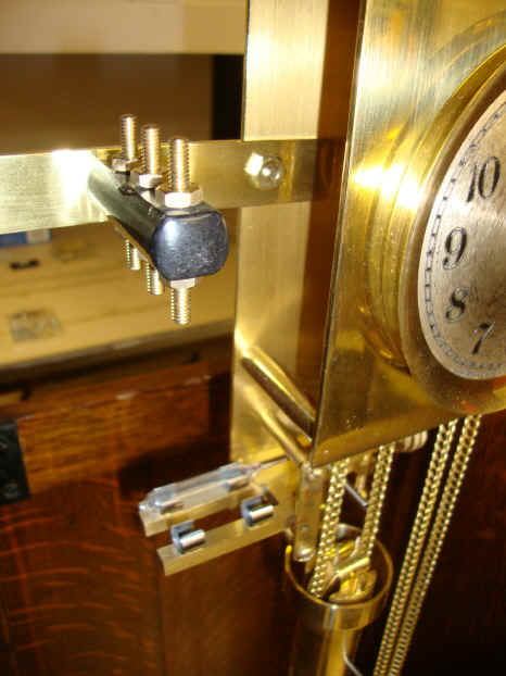
The tilt table and the electrical connector post installed. The screws on the post were later reduced in length.
|