|
Maker, Warren Telechron, Inc., Ashland, Massachusetts, USA. Model Type C, 1926, serial no. 7. Page 4. Restoration. General cleaning and repairs, movement After all of the missing parts were fabricated they were installed into the movement and the clock was tested for functionality. Once this was confirmed the entire movement was disassembled for a typical cleaning. The movement had 256 parts.
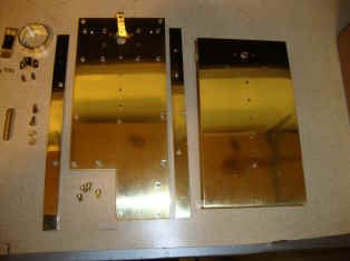
First the movement is disassembled. Other than the missing parts it was in very good 'as found' condition.
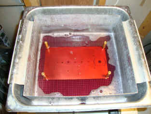
Non-flammable, degreaser and ammonia-free brass cleaner was used to get the parts into a clean condition. Afterward Simicrome metal polish brought about a high finish. The parts were then again put into the ultrasonic cleaner to remove all traces of the polish. The two main plates originally had a vertical grain finish which was retained.
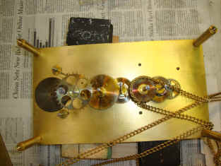
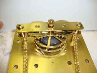
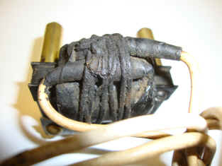
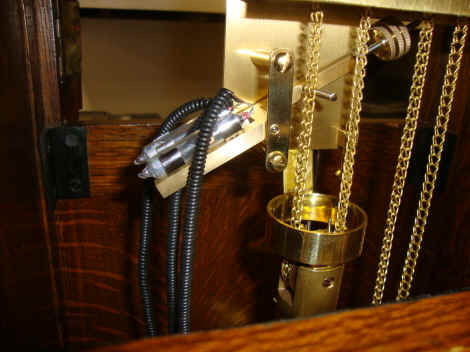
The first photo above shows the friction clutch mechanism that is used to advance or retard the chain, thus advancing or retarding the slave clocks. Reassembly was a bit tricky given the entangling chain drive as well as the clutch mechanism on the top plate.
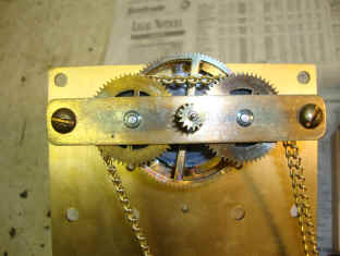
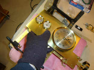
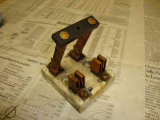
The completed movement. I allowed the plates to be exposed to the air for two weeks to allow just a bit of a mellowing color that I like on brass. The plates were then treated with Renaissance crystalline wax to prevent further tarnishing. Notice the fact that I use a gloves. From this point on I will not touch the plates. This type of protective coating is quite fragile and I chose it because the movement is protected within a wood and glass case with no possibility of anyone touching the metal. This is my first use of this material and I'm interested to see how well it performs over the years. Next the knife switches are cleaned and restored. The knobs were missing, but fortunately stock knobs that looked very much like those on the extant wooden case connection block were available.
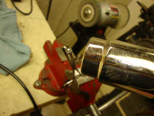
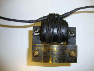
Wherever screws where originally blued, but corroded, I first cleaned, finished and polished the screw. Then using a heat gun re-blued the screw to the appropriate color. This screw was used to secure the knife switch to the wood case. Next. I replaced the white zip cord wire that was attached to the existing motor coil and was itself a sloppy repair. I used NOS wire that replicated the type of cloth wire that would have been used at the time and insulated the solder junction with shrink tube for a neat fit. The case tag in the last photo of the prior row shows the serial number of seven and the voltage being 110 and the cycles 25. This matches the cycles on the motor tag of the one motor that was with the clock when received (shown). Also both tags are of a similar design, brass material with black foreground; both stating the manufacturer as Warren Clock Co., General Electric, Co., USA. This important because the motor tag has the most recent patent date as May 27, 1924. A small sticker on the rear case door which looks old, and otherwise might be subject to doubt, but with the corroboration of the motor tag seems to be correct in that this unit was first put into service on August 11, 1926. This brings into focus an interesting conclusion. The Type C was first introduced in 1920. Yet we have a unit of serial #7 being put into service in 1926. The Telechron company used a sequential serial numbering system on their master clocks. The motor tag would preclude anything earlier than 1924. Given the unusual frequency of 25 cycles and that they match up between the motor tag and the case tag it's safe to say the motor is original. This would seem to indicate that only seven of the Type C were produced from the introduction in 1920 through 1926, about one per year. This is in sharp contrast to the company's highly successful Type A which by this time had a production of somewhere around 400 and would explain the fact that there is only one example of the Type C, while dozens of the the Type A are known.
The completed movement, less the tilt-table and movement contact block. The rear view shows the motor before re-wiring.
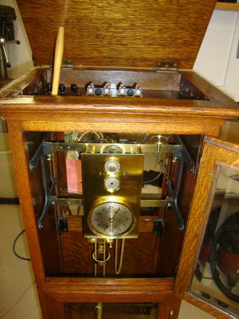
The clock was wired up using NOS type cloth wire, with the exception of the coiled wire that attached the mercury switches to the tilt table. The photos from the NAWCC article showed very thin, probably 35 AWG, solid core coils. I tried this type of wire, magnet wire with clear insulation and it did not look right, and it was still rather stiff. So I used a 24 AWG, braided, insulated wire and this had the right look and flexibility that I thought was appropriate. Unlike all other master clocks from the Telechron company this clock could not be wired up as originally from the factory and be expected to work normally. The clock was designed to run in a DC current environment and so needed rotary converters to operate properly. These converters were never a part of the clock itself, but were provided, along with a large control panel as additional units to be connected to the clock. These converters can be seen on page six describing the theory and functionality of the clock. They look to be quite large, certainly too large to fit within the case of the clock itself. Without these components the clock cannot function as designed. So I wired the synchronous motors to the tilt table. For this plan to work, however, the motor must run just a bit too fast, in other words run at a rate in excess of 60 cycles. This way the fast motor will cause the weight to rise faster than the clock unwinds the chain, thus raising the table and causing the circuit to open, stopping the motor. Now the clock can 'catch up' allowing the weight to fall and the table to tilt back, closing the switch and re-energizing the motor beginning the cycle again. Thus the weight is continuously raised to keep the clock running. If the motor runs too slowly the clock will run down and if it runs exactly as the master clock it will still not work because if the exact rate is achieved when the switch is open the clock will run down. If it is running when the switch is energized it will work but only as long as it is exactly in synch with the master clock. Suppose that the frequency today is controlled by atomic clocks, this will exceed the performance of the master clock and so they will not be exactly in synch. At some point an error will occur between the two rates and the clock will eventually stop or the weight will be over wound and lock up. The fail-safe way is to have a slightly fast motor. To do this I obtained a European 50 cycle synchronous motor made by Telechron, which, by the way is of the same dimensions as their US 60 cycle counterpart. So I simply slipped the 50 cycle rotor into a US coil and viola! You now have a rotor that would rotate at once per minute at 50 cycles per second now being driven at 60 cycles so the output is now 20% faster. It works perfectly for this application.
|