Edward J. Woolly fluid time lock, probably a demonstration or proof of concept model
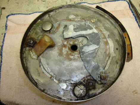
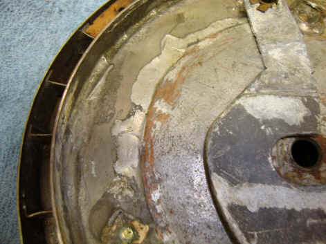
The first photo above shows the overall interior of the lock with the rear cover removed. The question marked shaped piece is made of sheet lead and can pivot at its base. This allowed for a smaller weight since it pivots outward as the moves clockwise giving greater inertia as it approached the outer circumference. It also allowed for less fluid to counterbalance than would have been necessary with a fixed weight. This was later replaced by a fixed weight in Woolly's patent application and the two known production production examples. Most likely because the movable weight proved unreliable. Notice the overall sloppy construction, shown more specifically in the second photo with regard to the soldering joints. The rear cover was held by bolts that screwed into nuts which were roughly soldered to the base of the lock.
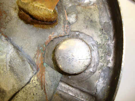
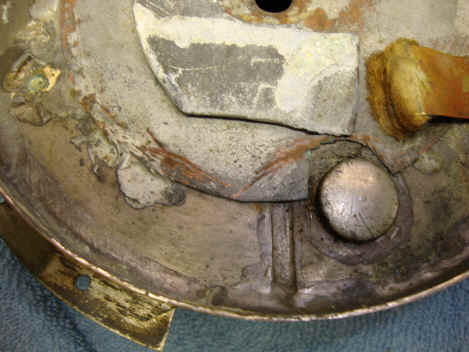
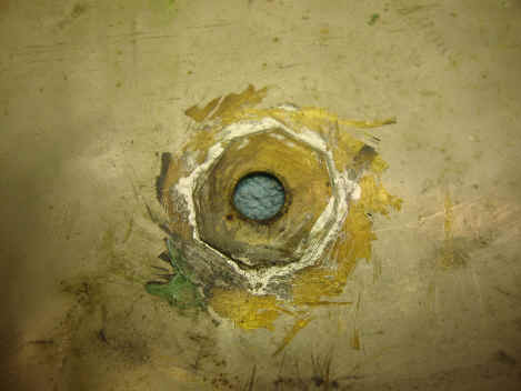
A copper sheet is soldered to the fluid tank which is a sealed doughnut shaped container beneath. This sheet covers the center of the tank doughnut and is where some of the lock components are mounted. Note how it is roughly cut around one of the fluid chamber's seals. The piece just above the fluid seal is part of the movable weight and the orange part is the stop upon which the weight rests when the lock is started.
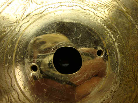
The inside rear plate contains one of the bushings upon which the lock rotates. A simple affair cut from brass sheet with no regard to craftsmanship. The front cover, which besides being decorative, also serves as the front structure for the fluid doughnut chamber; its center hole being poorly cut by hand. All of these observations makes it difficult to believe that this device was meant to be marketed as finished product. In particular a bank safe time lock whose requirements by their nature had to be precise, well built and most of all reliable. None of these requirements would this specimen fulfill. However, as a model for a proof of concept this would do.
|