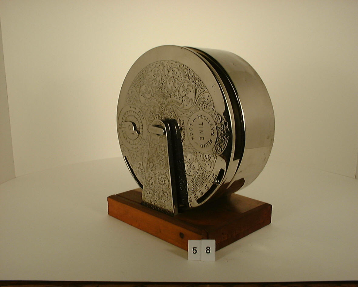
Edward J. Woolly fluid time lock, probably the patent or demonstration model
The patent describes the lock as follows: A cylindrical case is filled with a liquid and turns on its axis. ere are two chambers formed by a transverse partition, C. Small orifices at the bottom of C allow the liquid to pass from n to n’. A weight, W, is secured to a portion of the case. When the bodies of liquid in the two sections of the case are level the weight will cause it to rotate so that one of the cells, I, is brought into line with the tongue of the boltwork, G, so that it can enter the cell and permit the bolts to be withdrawn. At other times the solid periphery of the cylinder will present a barrier to the movement of the bolts.This time lock is the only one that did away with any mechanical clock or watch mechanism to regulate the lock. It relies on an asymmetrically weighted cylinder which is divided into two chambers. Refer to the patent drawing above. The two chambers are of equal volume with one having the weight, (Fig. 1). The chambers are pivoted from the center. The one chamber with the weight will naturally induce rotation, in this case clockwise. As the chambers rotate, fluid is forced through a needle valve (fig 4), from the left hand chamber, n to the right hand chamber n'. The needle valve regulates the rate at which the fluid will pass and thus the rate at which the entire cylinder will rotate. A graduated scale with adjustable blocks along the periphery allowed the operator to decide when the bolts, G would be able to be slid between the blocks, thus allowing the safe to be opened, (Fig 1 and 3). The last photo shows the reverse side of this scale. The wood block to the far right could be removed and moved to the open hole to the right of it, (see seventh photo close-up) allowing the bolt to either slide a bit sooner or later. The rest of the compartments appear to be reserved for ballast to adjust the cylinder. Indeed, the fifth compartment has a small lead weight with others either having wood or being empty, although they may have had either in them at one time. The scale is numbered 1 through 16, presumably hours, so weekend protection was an impossibility with this model. The top edge of the scale, photo four, is marked 59. There are no other markings. As one can see it is not as flexible a design as demonstrated in the patent drawing. The flimsy and 'home shop' way makes this example appear to be demonstration or proof-of-concept models rather than a polished commercial product. Internal solder joints and structural elements are rough and inconsistent, suggesting a prototype more than a finished vault product. Notably, the design includes an adjustable wood block marker on the cylinder’s periphery—this block determines when the bolt can slide and unlock the safe. It could never have had the accuracy to allow differing times of opening nor was the construction robust or reliable enough to have been used in the heavy environment of a safe door. The two examples in the Mossman collection are far better made. The only stout part on this lock is the quarter-inch thick circular name plate with the patent date of January 16, 1877. I believe this was a later addition to this artifact. In theory the design was a neat idea in that it eliminated all the reliability and maintenance problems associated with complex mechanical movements. Presumably it was also cheaper to make. In practice it proved to be too difficult to regulate precisely (a common problem with water clocks throughout history). Also in keeping with the rule of redundancy, there would still need to be two of these for each safe; making their coordination difficult. It means that over twice the space is needed on the safe door to accommodate this arrangement than a contemporary dual time lock like Sargent and Greenleaf's #2 or Yale's Model #1; space being at a premium in all but the larger doors. As a result few or any were made for commercial use. The only two models known to exist are in the Mossman museum. This example, due to it's fragile construction was probably not a production example. Still it is an extraordinary and rare time lock. Case #59. 6.5"diameter (without scale) x 3 deep. Original fluid still present. file 128
Exhibition example, probably the only "finished product" example known. This is in the Mossman Collection at the General Society of Tradesmen and Mechanics Museum in New York City.
|