Holmes Electric Time Lock Company, New York, NY, Model 1, Model 2, Model 3
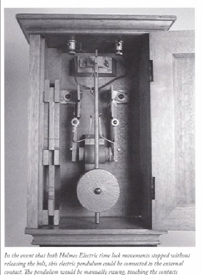
In the late 1870's the Holmes Electric Time Lock Company debuted its first of four models, of the Holmes Electric time lock. Charles Chinnock, a Holmes employee, first applied for the patent underlying the design in 1876, but was not granted until April 1, 1879, and though the Holms model may have been made prior to the patent date, no examples from the pre-patent period are known. Interestingly, engraving on the Holmes Electric also claims an 1872 patent assigned to Holms by Isaac and Abraham Hertzberg for an "apparatus automatically regulating flame of gas burners." The relevance for a patent for an automatically regulated gas burner is not entirely clear, although this may have been an attempt at patent priority. Throughout the time lock-related litigation, a number of diverse patents were relied on for priority with little success. The first movement movement production order was from E. Howard in July 1879 for 105 time locks. The two E. Howard movements are of the same dimensions that E. Howard used for Yale's Double Pin dial and some of the components were interchangeable. A small "disabling latch" on the lower right of the front plate, which keeps the time lock from closing, avoiding accidental time-locking of a safe during the business day. Such a latch would not appear on a Yale design until after 1900 or on a Sargent design until after 1920. The two movements turn a single twenty-four hour central that sets an opening period during each day, allowing the user to set the daily lock and unlock times once and simply wind the time lock thereafter. The major innovation in the Holmes Electric was its backup system, the main feature of the patent by Chinnock, a two pendulum electromagnetic mechanism visible across the top of the case. During installation a wire was connected to the contact visible on the top of the case (see example below) and run to a contact on the exterior of the vault door. In the event that both timers failed, the external contact was connected to an independent pendulum that was manually moved back and forth, sending pulses to two solenoid coils in the time lock that advanced the movements until the lock released ( see photo of that unit below).¹ Other time lock makers during this early period had other schemes to override the time lock should it fail, but only Holmes used an electromechanical design. Consolidated's Concussion, and calendar timer and Lewis Lillie had employed direct mechanical means. The reason for Holmes electrical approach was because these time locks were used in large vault installations making mechanical concussion impossible, while the others were meant to be used in smaller retail safes where access with a sledge hammer to mechanically active the concussion needed to override the time lock was practical.
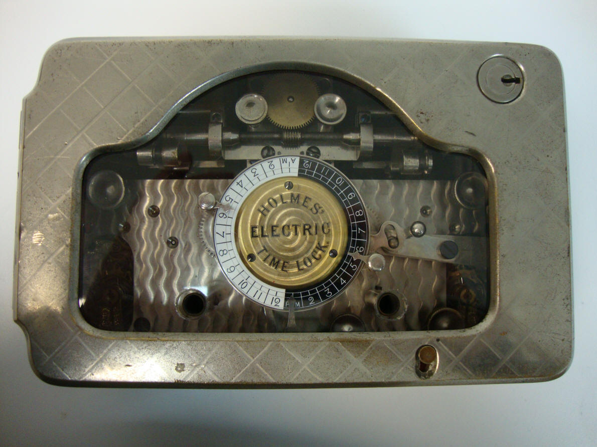
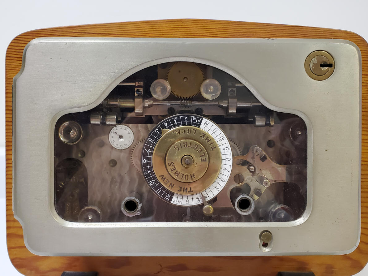
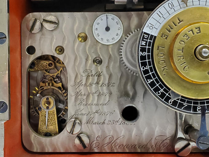
Patent drawings in connection with the first version of the Holmes Electric Time Lock applied for in 1876 but not granted until April 1, 1879, #213,809. A. (Edwin) Holmes Electric, Model 1, c. 1879. This is an example of a rare subset of time locks. So called 'transitional' time locks. These were produced for a brief period of time during the early development of the time lock when the reliability of the mechanical watch movements were not fully trusted. So a secondary way of unlocking the vault door was devised in case of their failure. This lock had an electrical system fed by low voltage batteries which would, in case of failure of both time lock movements, unlock the mechanism. Soon it was realized that this was not necessary as the movements rarely failed and with the fact that they were devised with at least one or two (later sometimes three) additional redundant movements the chances of complete failure becomes very remote. The very fact that a way to override the time lock existed in these transitional models, violated the basic purpose of the time lock concept - that the door could not be opened under any circumstances before the appointed time. The Model 1 had the dual pendulums on the inside rear of the case. This would later be moved to the outside of the case in their Model 3. For another example of such a transitional lock see the Consolidated time lock combined with an emergency secret combination lock here. The lock could be set for day or night operation. This lock is a very early example as there are no patent dates found on the movement (see below). The diamond machined pattern on the case and the camel back window design as well as the door hinge configuration closely match those of the Edward Stewart time lock made at about the same time. The interior features the original "security red" paint color. 7 7/8"w x 5"h x 3 1/4"d. Case #150, movement #199. file 142
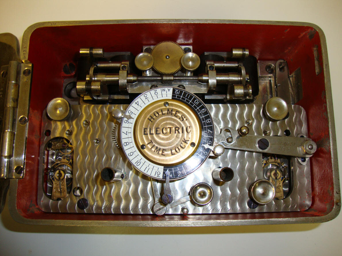
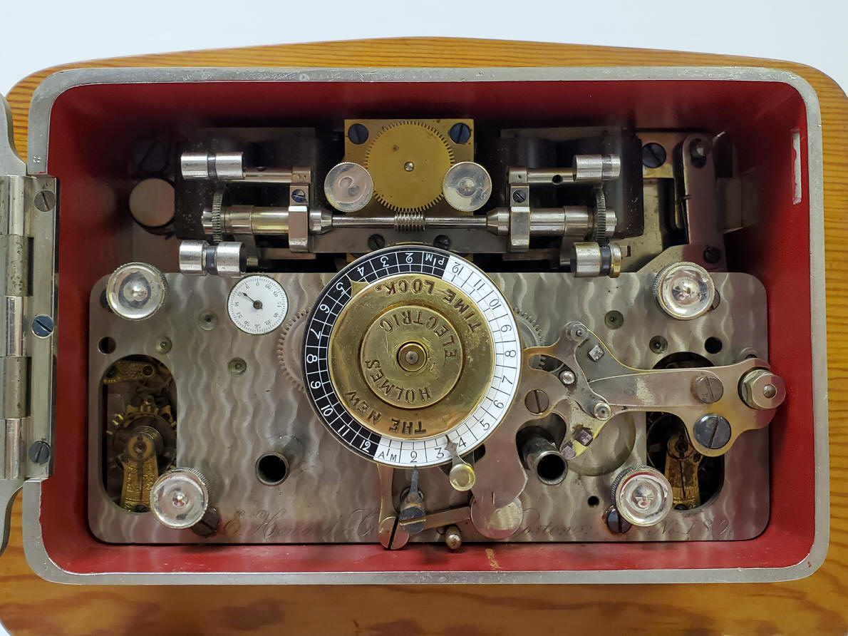
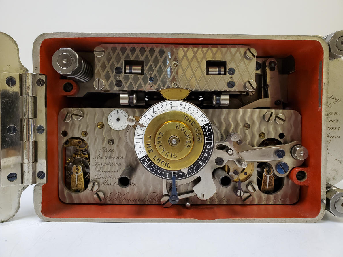
B. (Edwin) Holmes New Electric, a.k.a. Model 2, c. 1881-2. In 1882, Henry F. Newbury, a Holmes employee, found that the Yale and Sargent locks were vulnerable to a small charge of dynamite detonated against the door. Such an explosion could release or disable those time locks. Soon after Newbury was granted a series of nine anti-concussion patents. This version included those technologies. A subsidiary sixty-minute dial was added to allow the operator to more accurately set the lock and unlock times more accurately. It also included the "weekend mechanism" that allowed the time lock to skip one or two days of the scheduled opening, and a small button on the outside of the case door allowing the disabling latch to be operated without access to the the time lock itself. The releasing pair od pendulums remained on the inside rear of the case. The interior features the original "security red" paint color. 7 7/8"w x 5"h x 3 1/4"d. Case #22, movement #180. file 343
Model 3 incorporated the same seventy-two hour movement as the Model 2 allowing for the skipping of days for weekends. That device is the small circular copper colored disk near the 4 o'clock position of the main center dial, second photo.
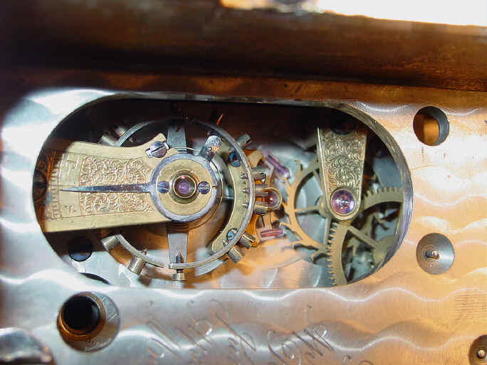
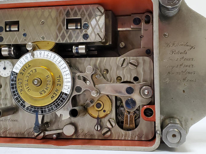
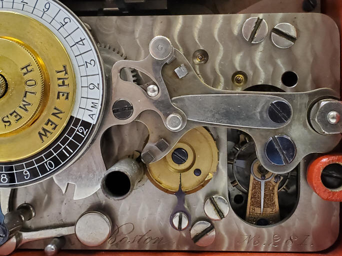
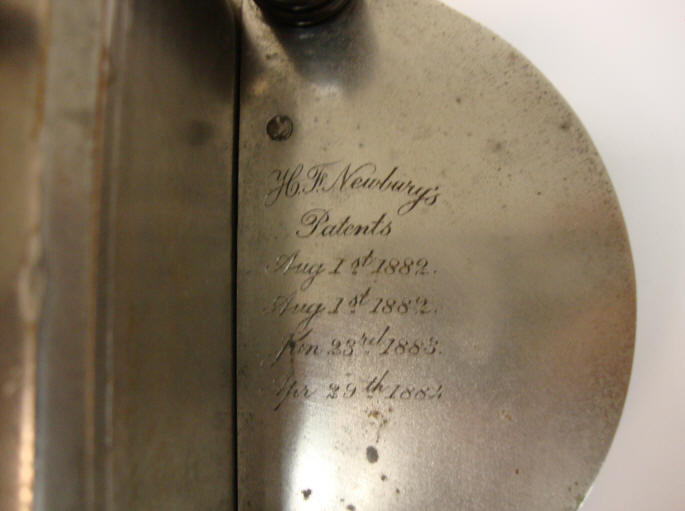
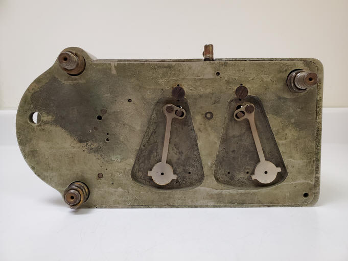
Demonstration of Holms time lock Model 3. Note the lock in the video is not the same as the one illustrated above, this one is the identical model, but movement serial number 350. The first photo shows the patent plate that appeared in the Holmes second iteration of their second model. These show Henry F. Newbury's patents. In 1882, Newbury, a Holmes employee, found that Yale and Sargent time locks were vulnerable to a small charge of dynamite detonated against the safe door. Such an explosion could either release or disable these time locks. Soon after, Newbury was granted a series of nine anti-concussion patents. The two 1882 patents and the January 1883 patents match any patent on record with the Patent and trademark Office, but they may refer to the anti-concussion patents. There is some speculation that Holms intentionally misdated the plaque. While Newbury did have patent protection, this was useful only if Holmes could identify infringing time locks - a difficult task, since Newbury's anti-dynamite designs were subtle changes in the internal construction of the time lock. Hence, Holmes may have included these dates to advertise that the technology was patented while trying to keep the published details obscured. The fourth patent date of April 29, 1884 and is #297,623 is for the New Electric design itself. The plate is part of the bolt pivot mount used in conjunction with the the bolt release within the lock.¹ The second photo shows a pair of pendulums located in recess areas within the back of the lock. These pendulums are connected to coil paddles in the photo below and prevent those paddles from being pushed too fast. The inertia provided by the pendulums prevent someone from trying to override the time lock too quickly. This provision was necessary since the Holmes gear ratio between the paddle ratchets and the final override connected to the main dial was relatively low. No one wanted the override to be used to by pass the time lock unless the lock failed and so the idea was that anyone trying to override the the time lock would need to take so much time as to either be authorized or if otherwise, would be discovered in due course before successfully bypassing the the time lock. The Concussion timer made by the Consolidated Company was another example of a time lock override system but used a very high gear ratio to get around this problem. In that case the operator could not override the lock quickly because of the very high number of turns one needed on the input verses the output gear that actuated the override mechanism.
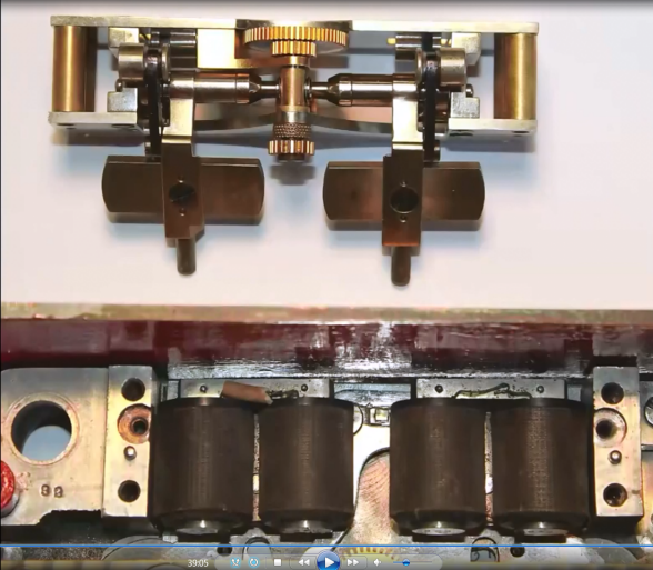
The upper section of the first photo shows the mechanical paddles. The pair of rods near the bottom are what insert into the pair of pendulums shown in the photo of the rear of the time lock above. The lower photo section are the pair of coils that electrically actuate each paddle sequentially thus advancing the center gear seen in the same photo. The second photo shows the device used to electrically actuate the paddles. It has a pendulum which connects to contacts which, in turn, actuate the coils within the time lock, activating the paddles, slowed by the pendulums located behind the time lock and driving the center gear to override the time lock, see video below. One can see how without the moderating pendulums within the time lock itself, someone could simply grasp the pendulum on the external pendulum unit and try to quickly override the lock. Similarly one could simply take two wires from the system and quickly tap them together.
This video demonstrates the Holmes Time Lock Model 2 electro-mechanical override system, c. 1882. A few time lock makers wanted to be able to override the mechanical time lock should there be a catastrophic failure of the mechanical timer movements. Usually these timers are in pairs to prevent just such a failure, but given a large enough explosive charge there could be damage to both, thus without an alternative method of putting the lock 'off guard' would result in a lockout. Now the fact is that such a large concussion would probably result in damage to the electro-mechanical override system, but it still was a good marketing tool. To best of this author's knowledge Holmes was the only company to use an electromechanical design to achieve this. The other company to use an override was the Consolidated Time Lock company, but theirs was a purely mechanical system. There was one other company that introduced an electromechanical system into a mechanical time lock was the Hollar company's Model 1 and Model 2 that used a motor not to override, but to extend, the duration of the time lock past the maximum time on the dials in case of an emergency such as civil disturbance or riot by rewinding them from a control outside the vault. The pendulum pair here are on the inside rear wall of the case, this was the configuration used in their Model 1 and Model 2. Their last time lock, the Model 3 shifted the position to the outside of the rear case was presumably to be more explosive-resistant. Again, in this author's opinion an explosion that would get to this area would most likely damage the override system.
Patent drawings in connection with the second version named the New Holmes Electric Time Lock, April 29, 1884, #297,623. C. Holmes New Electric, a.k.a. Model 3, c. 1885. It employed the same Henry F. Newbury, a Holmes employee, anti-dynamite patents described for Model 2. This version included those technologies, plus spring loaded bolts around case. It also had a design change where the pendulum release devices were moved from the rear of the case interior to the rear of the case exterior, presumably to further reduce the possibility of derangement in the event of explosion. This also incorporated a redesigned and smaller yet more resilient electromagnetic mechanism which was for the first time covered with a decorative cross-hatched plate.¹ The decorative flange (photo #1 and #5) illustrating these patent dates.² The movement also has patent dates for Holmes on the front movement plate in addition to the maker's logo - E. Howard & Co.; making this one of the more engraved locks. As with the second version (see above), it included the "weekend mechanism" that allowed the time lock to skip one or two days of the scheduled opening, and a small button on the outside of the case door allowing the disabling latch to be operated without access to the the time lock itself. By this time Holmes substituted plain screws for the decorative knurled bolts to secure the components within the case and moved the electromechanical pendulums from the inside to the rear backside of the case and vault door. This change was probably made to further counter the use of explosives.¹ The interior features the original "security red" paint color. 7 7/8"w x 5"h x 3 1/4"d. Case #2, movement #281. file 239 This was such a highly regarded time lock that both E. Howard, the company that made the movements for most of the time lock industry, and the U.S. Treasury Department used it. Unfortunately for Holmes this corporate snub brought down the ire of the much more powerful Yale company, resulting in a patent infringement lawsuit and the end of the Holmes Electric Time Lock Company. Of the 350 or so Holmes time locks produced only ten are known today.¹ Of those three are of the first version, with the remaining of the second version. Below a Holmes mounted in a Herring Hall double dial vault door. Below is a photo of a Holmes Model 1 mounted to a safe door.
(1) American Genius Nineteenth Century Bank Locks and Time Locks, David Erroll & John Erroll, pp 210.(2) American Genius Nineteenth Century Bank Locks and Time Locks, David Erroll & John Erroll, pp 209.
|
 A
A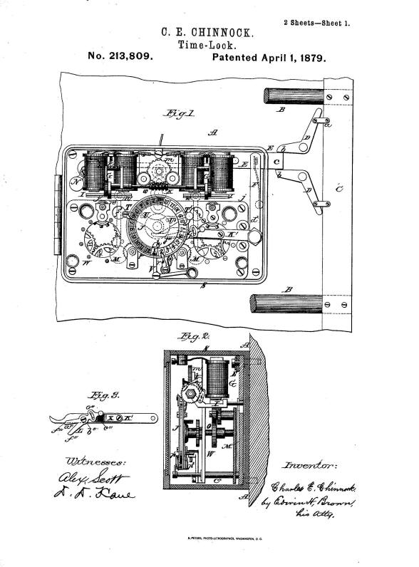

 B
B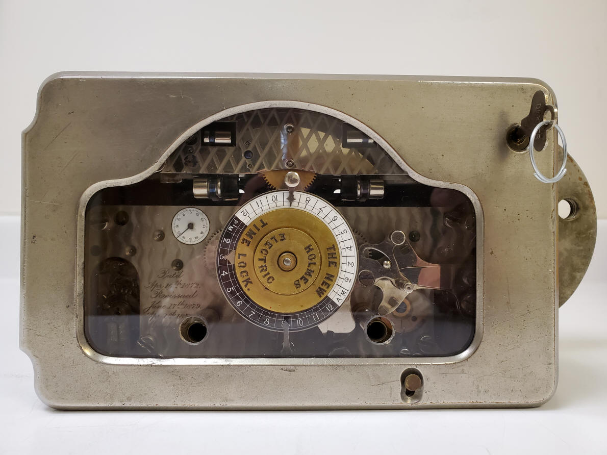
 C
C